

A pilot's first encounter with a busy chart can feel like a wall of colors, abbreviations, frequencies, altitude numbers, and lines with no obvious starting point. Chart interpretation is the process of turning that visual clutter into an operational picture, so a pilot can identify the route, altitude limits, airspace, communications, terrain, and required actions. The most reliable method isn't memorizing every symbol in isolation. It's scanning the chart in a consistent order and giving priority to information that can change the flight's safety or legality.
Table of Contents
- Introduction to Pilot Chart Interpretation
- Systematic Workflow for Approach Plates
- VFR Sectionals vs IFR Terminal Charts
- Visual Search and Prioritization Strategies
- Decoding Altitudes and Frequencies at KCNO
- Common Mistakes and Pre-flight Checklist
- Chart Interpretation FAQs
Introduction to Pilot Chart Interpretation
A student departing Chino Airport may be looking at a sectional while tracking a busy Class D boundary, nearby controlled airspace, rising terrain, and several airports competing for attention. The chart may show the correct information, yet the pilot can still feel uncertain because the information is spread across different visual layers. A frequency may be easy to spot while an altitude restriction remains overlooked, or an airspace boundary may appear clear without making its vertical limits immediately memorable.
That gap between seeing a chart and understanding its operational meaning is where chart interpretation matters. It connects a flat graphic to a three-dimensional mental model of the flight. The same skill supports a private pilot planning a cross-country flight, an instrument student briefing an approach, a renter checking airport information, and a career-track pilot preparing for a checkride.
Chart interpretation developed from the need to make relationships visible. Historical chart design moved from numerical tables toward visual systems for comparing quantities, trends, and proportions. William Playfair's 1786 publication, Commercial and Political Atlas, is widely associated with modern line graphs, bar charts, and time-series displays, while Charles Joseph Minard's 1869 visualization of Napoleon's Russian campaign combined geography, direction, distance, army size, and temperature in a single graphic. The underlying lesson still applies to aviation charts: visual elements should make important relationships apparent without forcing the reader to reconstruct them from scattered information. This history of chart interpretation and visual encoding explains that enduring principle.
The operational questions behind every chart
A pilot doesn't need to begin by naming every symbol. The first questions should be practical:
- Where is the aircraft going? Identify the route, fixes, runway, airway, or corridor.
- What can restrict the route? Check terrain, obstacles, airspace, special-use areas, and procedure notes.
- Which altitude controls? Separate minimums, maximums, mandatory altitudes, and recommended altitudes.
- Who must be contacted? Locate the applicable frequencies and confirm their purpose.
- What changes the plan? Review notes, revisions, weather-related limitations, NOTAMs, and missed-approach instructions.
This approach helps a pilot manage Southern California's visual density without treating every item as equally urgent. It also transfers nationwide. A chart around a quiet rural airport may contain fewer visual distractions, but the same questions still determine whether the planned flight is understood correctly.
Practical rule: A chart isn't a picture to admire. It's a set of operational relationships that must be verified before the aircraft depends on them.
Systematic Workflow for Approach Plates
An instrument approach plate should be read as a structured procedure, not just as a map of the airport. The FAA divides an instrument approach procedure into six operational sections: chart identification, pilot briefing and notes, plan view, profile view, landing minimums, and airport diagram. The FAA instrument flying handbook provides the foundation for this sequence.
Start with identity and notes
The first scan confirms the airport, runway, procedure name, and chart revision. A pilot should verify that the procedure matches the clearance and the intended runway before studying the route itself. This catches a basic but consequential error, briefing the wrong procedure because two nearby airports or runway numbers looked similar at a glance.
The notes section comes next. It may contain communication requirements, equipment considerations, authorization conditions, restrictions, or special instructions. These notes aren't background material. They can determine whether the procedure is available to the aircraft and crew.
Trace the lateral route
The plan view shows the route from the initial fix through the intermediate and final segments, then toward the missed approach. Intersections, fixes, radials, bearings, and course lines should be traced in the same direction the aircraft will fly them. A pilot briefing an approach at a towered airport such as Chino should verbalize each transition rather than relying on a quick visual glance.
A useful verbal pattern identifies:
- The entry point, including the expected transition or initial fix.
- The route sequence, including turns, courses, and named fixes.
- The final approach, including alignment and the point where descent is authorized.
- The missed approach, including the initial heading, altitude, and holding or routing instructions.
Read vertical information separately
The profile view answers a different question from the plan view. It shows altitude restrictions, descent sequencing, step-down fixes, vertical guidance, and the relationship between the route and the runway. A pilot should check each altitude against the associated fix instead of reading the profile as one continuous slope.
The final pass covers landing minimums and the airport diagram. Straight-in and circling minimums aren't interchangeable, and decision altitude or minimum descent altitude must match the type of approach and available guidance. Frequencies, headings, altitudes, and minimums should be cross-checked against the aircraft's navigation setup before entering instrument conditions. Training resources on instrument approach procedures can reinforce this briefing discipline.
VFR Sectionals vs IFR Terminal Charts
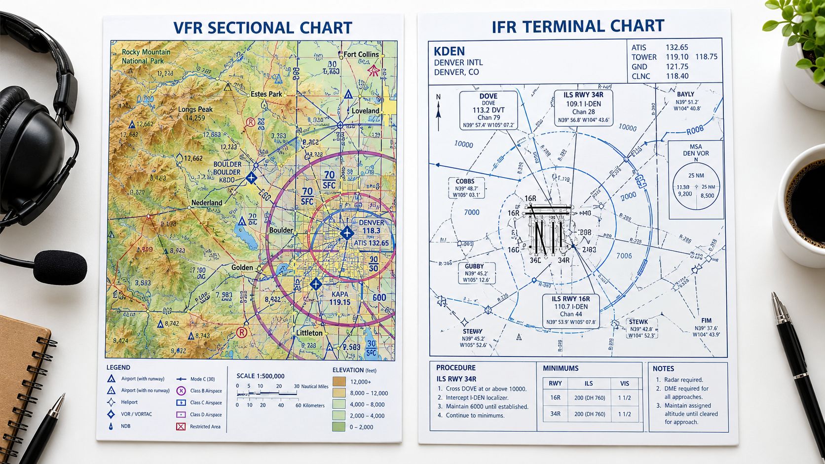
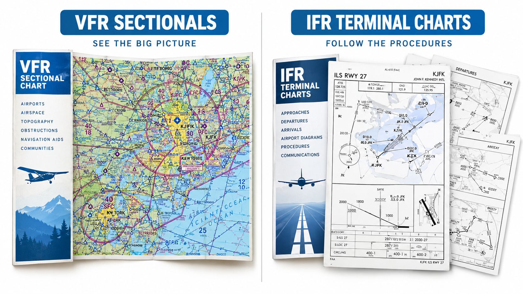
A VFR sectional and an IFR terminal chart may cover the same region, but they answer different operational questions. The sectional helps a pilot understand visual navigation, terrain, landmarks, airspace, airports, obstacles, and route hazards. The IFR terminal chart organizes a published procedure, its fixes, courses, altitudes, communications, and approach minimums.
The same visual instinct can cause trouble on both. A pilot may recognize a color or line from one chart product and assume it carries the same meaning on another. FAA charting guidance treats symbols as product-specific, so the legend is a required reference, not optional reading. The FAA Chart Users' Guide explains the charting conventions used across VFR sectionals, terminal-area charts, low-altitude IFR charts, and terminal procedures.
Different charts, different priorities
| Chart type | Primary question | Information that deserves early attention |
|---|---|---|
| VFR sectional | Can the pilot navigate visually while avoiding hazards and unauthorized airspace? | Airspace boundaries, terrain, obstacles, airports, landmarks, frequencies, and special-use areas |
| IFR terminal chart | Can the pilot fly a published instrument procedure correctly? | Procedure identity, fixes, courses, altitude constraints, communications, minimums, and missed approach |
| IFR enroute chart | How does the aircraft move between terminals? | Airways, navigation facilities, route structure, altitudes, and communications |
A sectional's terrain shading can support threat recognition, but it doesn't authorize a route or replace the regulations governing airspace entry. Likewise, a procedure line on an instrument chart defines a published route, but it doesn't remove the need to confirm clearance, equipment, communication, and aircraft capability.
Treat symbols as layers
A sound review combines several layers instead of relying on visual intuition:
- Airspace classification, including lateral and vertical boundaries.
- Terrain and obstacle information, including elevations that affect route selection.
- Navigation facilities, their status, and their relationship to the route.
- Communication requirements, including the purpose of each frequency.
- Procedure notes, which may alter how the chart is used.
International operations add another reason to verify the governing standard. ICAO Annex 4 provides internationally standardized chart formats, content, and symbols, while FAA guidance supplies United States terminology and implementation. A pilot transitioning between U.S. operations and international procedures shouldn't assume that units, minima presentation, procedure notation, or symbol conventions are interchangeable.
Before a VFR cross-country, a structured VFR cross-country flight planning review can help connect the sectional's visual information to the planned route, checkpoints, fuel strategy, airspace, and communications.
Visual Search and Prioritization Strategies
Chart interpretation is often taught as a vocabulary exercise. A student learns what a symbol means, passes a quiz, and then faces a real chart where symbols overlap, labels compete for space, and several restrictions appear near the same route. The harder skill is deciding where to look first and what information controls the decision.
The FAA's 2025 Chart Users' Guide is primarily a reference for chart symbology, and it warns that its graphics are educational and not for navigation. That distinction matters. A pilot may understand a symbol perfectly and still apply it incorrectly during flight planning if the chart product, scale, note, or governing procedure is different.
FAA human-factors research found that pilots generally used a serial visual-search strategy and made disproportionately more errors on questions involving altitude constraints. The practical lesson is clear: altitude information deserves deliberate attention rather than a casual glance. FAA aeronautical chart guidance provides relevant background for building that habit.
A scan sequence for cluttered charts
A useful sequence moves from broad hazards toward details:
- Route hazards come first. Identify terrain, obstacles, restricted or special-use areas, and nearby traffic conflicts.
- Altitude constraints come next. Find the controlling minimum, maximum, mandatory, or assigned altitude at each critical point.
- Airspace boundaries define where the aircraft may operate and what communication or clearance requirements apply.
- Frequencies support the communication plan, but they shouldn't distract from the route and altitude picture.
- Currency and notes provide the final check. Confirm revision information, procedure availability, and operational remarks.
This order doesn't mean a frequency is unimportant. It means the pilot avoids spending early attention on an easy-to-read detail while missing a less visually prominent altitude restriction.
Resolve conflicts by asking what each item represents
When terrain, an obstacle, airspace, and an instrument procedure appear together, they don't all perform the same function. Terrain and obstacle information support clearance planning. Airspace boundaries define regulatory limits. Procedure altitudes establish the vertical path for a published approach. A clearance, regulation, procedure note, or aircraft limitation may control a particular decision, so the pilot must identify the source and purpose of each item rather than choosing the most visually prominent number.
The contrarian lesson: Chart interpretation isn't mainly a memory test. It's a visual-search and prioritization skill.
A tablet or electronic display can reduce folding and physical handling, but it can also introduce clutter through layers, labels, and zoom changes. The pilot should preserve the same scan sequence on paper or electronically and avoid treating a clean display as proof that the interpretation is correct.
Decoding Altitudes and Frequencies at KCNO
Altitude markings on an instrument approach chart carry operational meaning. The FAA states that an underscored altitude in the profile view is a minimum altitude, so the aircraft must remain at or above that value. An overscored altitude is a maximum, while an altitude with both markings is mandatory. The FAA's approach chart guidance explains these conventions.
Read the marking before reading the number
A pilot briefing an approach into KCNO should use this order:
- Identify the fix or segment. An altitude only has meaning when connected to its location on the procedure.
- Inspect the formatting. Determine whether the altitude is a minimum, maximum, or mandatory restriction.
- Compare it with the assigned clearance. An assigned altitude may be higher than a procedure minimum, but a pilot shouldn't descend below a published restriction without authorization and compliance with the procedure.
- Confirm the next constraint. The next fix may carry a different altitude or descent requirement.
- Cross-check the aircraft setup. The selected altitude, navigation source, and flight director or autopilot mode should agree with the briefed procedure.
For example, an underscored altitude at an intermediate fix means the aircraft must cross that fix at or above the published value. An overscored altitude indicates that the aircraft must not exceed the published value at the relevant point. A mandatory altitude requires compliance with that specific restriction, not a guess based on the apparent angle of the profile line.
Distinguish DA from MDA
Approach minimums also use different concepts for different kinds of guidance. Decision altitude or height, shown as DA or DH, applies to approaches with vertical guidance such as LPV or LNAV/VNAV. Minimum descent altitude, shown as MDA, applies to lateral-only procedures such as LNAV or LP.
A pilot flying a lateral-only procedure must not descend below the MDA unless the requirements of 14 CFR § 91.175 are met. The correct response at minimums depends on the required visual references and the aircraft's position relative to the runway environment, not on a desire to continue the approach.
Build the frequency picture
The communication panel should be read as a sequence rather than as a list. A pilot can identify the relevant approach, tower, ground, clearance, and airport information frequencies, then match each one to the phase of flight. Frequency verification should include the chart label, expected runway or procedure, aircraft radio setup, and any current operational information.
At Chino, a pilot may be managing a towered airport, surrounding controlled airspace, and a high-workload arrival or departure. A written frequency plan reduces head-down time and helps prevent a pilot from tuning a familiar frequency that serves a different function. Reference material on flight service frequencies can support broader communications planning.
Common Mistakes and Pre-flight Checklist
Many chart errors happen because the pilot recognizes the general picture and stops before verifying the details. A sectional may look familiar, or an approach plate may resemble one used previously, but a similar layout doesn't guarantee the same altitude logic, frequency, runway, or procedure status.
The most serious mistakes usually involve priority, not symbol recognition. A pilot sees the airport, route, and runway but misses a controlling altitude. Another pilot notices the correct frequency but fails to review a note that changes how the procedure must be flown.
Mistakes that deserve deliberate correction
- Reading visual prominence as operational priority. Large labels and bright colors attract attention, but the most important restriction may be small and attached to a fix.
- Confusing altitude types. A maximum altitude must not be treated as a minimum, and an MDA must not be handled like a DA.
- Skipping the legend. Chart symbols and colors are product-specific. Familiarity with one chart doesn't eliminate the need to verify another.
- Ignoring revision information. An outdated airport diagram, frequency, or procedure can create an incorrect mental model.
- Briefing only the approach segment. The missed approach is part of the procedure and should be understood before descent begins.
- Treating recommendations as regulations. Regulatory minimums establish a legal floor, while personal minimums and training margins may need to be more conservative.
For VFR pilots, the governing rule also matters. Under 14 CFR § 91.155, basic VFR operations in Class D airspace require at least 3 statute miles of flight visibility, and at or below 10,000 feet MSL, the aircraft must remain 500 feet below clouds, 1,000 feet above clouds, and 2,000 feet horizontally from clouds. The current federal regulation identifies these as regulatory minimums. They aren't personal or training minimums, and exceptions such as special VFR under § 91.157 may apply.
A practical pre-flight review
A pilot can use the following checklist before relying on a chart:
- Confirm the product. Is the chart a sectional, terminal-area chart, enroute chart, or instrument procedure?
- Check currency. Verify the chart date, procedure revision, airport information, and relevant operational notices.
- Build the big picture. Identify terrain, obstacles, airspace, restricted areas, airports, and route hazards.
- Follow the route. Trace each leg in the direction of flight, including transitions, fixes, turns, and missed-approach routing.
- Mark controlling altitudes. Separate minimum, maximum, mandatory, assigned, and recommended values.
- Review communications. Match each frequency to its purpose and phase of flight.
- Confirm minima. Identify whether the procedure uses DA or MDA and verify the applicable visibility and ceiling requirements.
- Cross-check the aircraft. Confirm navigation equipment, database information, performance, fuel, and aircraft limitations.
- Brief the abnormal path. Know the missed approach, diversion options, and conditions that would trigger a change of plan.
Turning the checklist into a habit
The checklist works best when the pilot says the critical information aloud. Verbalizing the route exposes gaps that silent scanning can hide, especially when several altitudes appear close together. During training, an instructor can also ask which item controls and why, rather than accepting a correct number without understanding its source.
A thorough chart review doesn't eliminate uncertainty. It gives uncertainty a place in the decision process. If terrain, weather, traffic, aircraft performance, or workload makes the planned route unsuitable, the pilot can delay, reroute, request help, or discontinue the approach before the situation becomes urgent.
DuBois Aviation provides private, instrument, commercial, multi-engine, CFI, CFII, MEI, and helicopter training at Chino Airport, along with aircraft rental, simulator support, and instruction that includes practical chart and procedure work. Pilots can visit DuBois Aviation to ask about course availability, schedule a school tour, or request training information focused on safer chart interpretation and confident decision-making.
Chart Interpretation FAQs
What is chart interpretation in aviation?
Chart interpretation is the process of converting charted information into an operational understanding of the flight. It includes identifying routes, airspace, terrain, obstacles, altitudes, frequencies, procedure notes, and minimums, then determining how those items affect the planned operation.
Should a pilot memorize every chart symbol?
No. A pilot should understand common symbols and know how to use the applicable chart legend. The more important habit is recognizing which chart product is in use and checking the legend when a symbol, color, or notation is unfamiliar or operationally important.
What should a pilot read first on an approach plate?
The first scan should confirm the airport, runway, procedure title, and revision. The pilot should then review notes and communications, trace the plan view, study the profile view, confirm minimums, and review the airport diagram and missed approach.
What does an underscored altitude mean?
An underscored altitude in the profile view is a minimum altitude. The aircraft must remain at or above that value at the associated point or segment. An overscored altitude represents a maximum, and an altitude with both markings is mandatory.
What is the difference between DA and MDA?
DA or DH is used with vertical guidance such as LPV or LNAV/VNAV. MDA is used on lateral-only procedures such as LNAV or LP. A pilot must follow the applicable approach requirements and may not descend below an MDA unless the conditions of 14 CFR § 91.175 are satisfied.
How can a pilot manage a cluttered Southern California chart?
A consistent scan helps. Start with route hazards, then altitude constraints, airspace boundaries, frequencies, and chart currency. The pilot should trace the route aloud and identify which source controls each important restriction instead of relying on the most visually prominent symbol.