
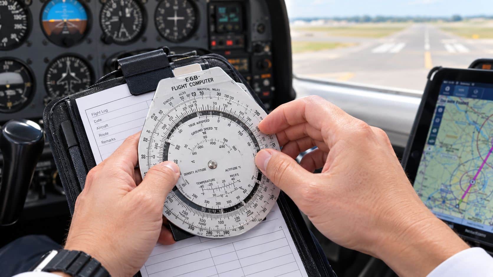
A student pilot at Chino Airport (KCNO) is setting up for a cross-country flight when the E6B slides across the kneeboard, the sectional is already marked, and the aircraft is waiting on the ramp. The immediate question is simple: how to use a flight computer E6B to turn course, wind, airspeed, distance, and fuel information into a usable flight plan. The process starts with learning the two sides of the device, then applying each answer to the next calculation.
Table of Contents
- What the E6B Flight Computer Does and Why It Still Matters
- Getting Familiar with the Front and Back of the E6B
- Solving for Wind Correction Angle and Ground Speed
- Calculating Time En Route Distance and Fuel Burn
- Working Out Density Altitude and Unit Conversions
- Using the Manual E6B Alongside a Modern Cockpit
- Practice Problems and a Pre-Checkride Checklist
What the E6B Flight Computer Does and Why It Still Matters
An E6B flight computer is a mechanical slide-rule analog computer for aviation calculations. The manual version uses rotating scales, a wind grid, and a center grommet instead of batteries or electronic menus. It helps pilots solve wind correction, groundspeed, time en route, fuel burn, endurance, density altitude, airspeed, and unit-conversion problems.
The modern E6B was developed in the United States by Naval Lt. Philip Dalton in the late 1930s and formally introduced to the Army in 1940. Its operational importance expanded rapidly after Pearl Harbor, when the U.S. Army Air Forces placed a large order and more than 400,000 units were manufactured during World War II (historical background on the E6B). That history explains why the device became more than a classroom aid. It was a practical navigation tool for pilots working with limited electronic equipment.
The cockpit value of a mechanical calculator
A GPS display can show a groundspeed. An avionics system can calculate fuel estimates. A tablet can display a flight plan. The E6B still earns a place in training because it shows why the answer changes when the wind, course, or airspeed changes.
That physical relationship matters during preflight planning and in the air. A pilot can use the E6B to check an electronic result, rebuild a calculation after an avionics problem, or identify an obviously unreasonable number. The manual device also develops a working mental model of the wind triangle instead of reducing every problem to a button press.
Practical rule: A mechanical E6B is a backup and a learning tool, not permission to ignore aircraft procedures, fuel requirements, weather information, or the approved flight-planning process.
Sporty's describes one E6B model as supporting 23 aviation functions and 14 standard conversions, including common tasks such as groundspeed, time, airspeed, distance, fuel burn, time en route, and density altitude (E6B functions and conversions). A pilot who becomes comfortable with those functions can move from isolated written-test exercises to a complete navigation log. Even a simple compass for navigation can complement the broader ground-navigation kit when a pilot is learning how direction, heading, and course relate.
Getting Familiar with the Front and Back of the E6B
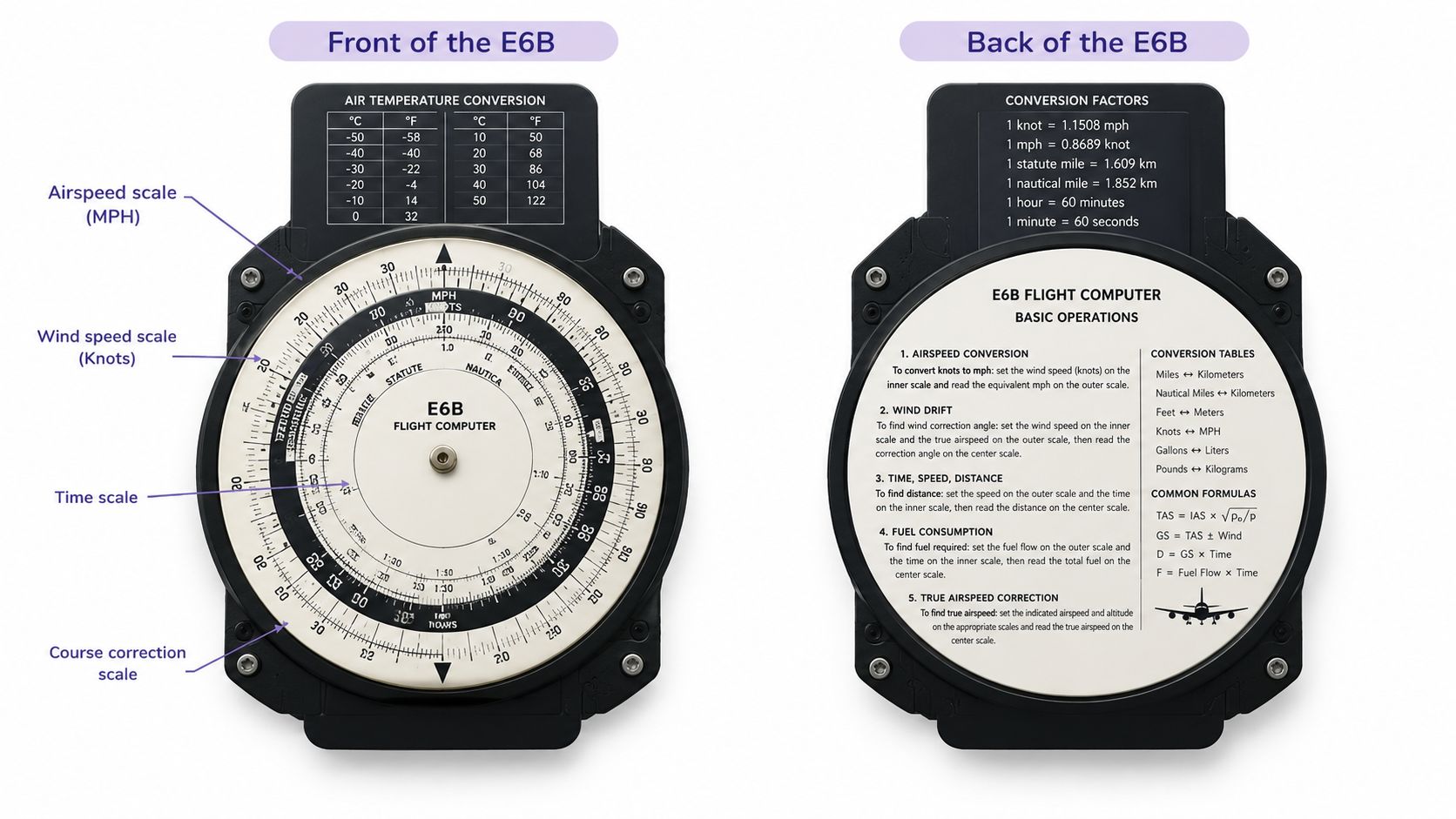
Before solving a problem, the student should be able to identify the working parts without turning the device over repeatedly. A standard E6B has a circular calculation side and a wind side. Different models may print the scales differently, so the aircraft pilot should follow the layout shown in the model's manual.
The circular calculation side
The circular side is used for ratios, multiplication, division, time, speed, distance, fuel, and conversions. The outer scale commonly carries airspeed values, while the inner scale carries distance and the clock-style time and fuel-flow values.
The rotating azimuth ring surrounds the central area. Its true index is the reference point used to align a course or direction. The speed arrow, often identified as the rate or airspeed index, helps position speed or fuel-flow information against the appropriate scale.
A quick ground rehearsal helps:
- Spin the azimuth ring and locate the true index.
- Find the airspeed arrow and identify the outer airspeed scale.
- Trace the inner scale and locate the time, distance, and fuel-flow markings.
- Turn the device over and identify the wind grid before trying to solve a wind problem.
The wind and correction side
The back contains a wind-direction grid, a true index, a center grommet, and a calibrated airspeed and temperature area used for corrections. The wind grid represents direction and velocity as a physical vector. Once the airplane and wind marks are placed correctly, the pilot can read wind correction angle and groundspeed directly.
The most common early mistake is confusing where the wind comes from with where it travels. A wind reported from 240 degrees is placed at 240 degrees on the grid. It isn't placed at the direction toward which the wind is moving.
A second mistake is reading the wrong scale. Every mark should be labeled with a short note such as TC, TAS, W, or GS. That small habit prevents a correct-looking answer from being attached to the wrong variable.
Solving for Wind Correction Angle and Ground Speed
The wind side turns the wind triangle into a hands-on procedure. The following KCNO planning example uses a true course of 270 degrees, a true airspeed of 110 knots, and wind from 240 degrees at 15 knots. These are practice inputs, not a weather report.
Set the wind and airplane marks
First, place the wind direction under the true index according to the layout of the particular E6B. The wind comes from 240 degrees, so the wind direction mark belongs at 240 on the azimuth ring. Place the airplane or airspeed dot at the true airspeed of 110 knots on the appropriate scale.
Next, use the center grommet to mark the wind velocity. The 15-knot wind is measured from the center and marked along the 240-degree line. A pencil mark is preferable to relying on memory, especially when several calculations will use the same wind.
Rotate the true index over the wind direction as directed by the model's instructions. The center grommet then shows the wind correction angle. The pilot applies that correction to the 270-degree true course. Because the wind is from the left of the westbound course, the heading correction will be toward the wind, subject to the exact E6B layout and the sign convention being used.
Read groundspeed and record the result
The distance between the airplane mark and the wind mark represents the resulting groundspeed. Read the value from the inner scale and write it into the navigation log with the units clearly marked as knots. The result should make operational sense. A crosswind can change heading without producing the same groundspeed change as a direct headwind or tailwind.
| Number | Label | Source |
|---|---|---|
| 270° | True course | Practice input |
| 110 kt | True airspeed | Practice input |
| 240° | Wind from direction | Practice input |
| 15 kt | Wind velocity | Practice input |
| Result | Wind correction angle and groundspeed | E6B reading |
A detailed ground speed calculation guide can help reinforce the relationship between airspeed, wind, heading, and movement over the ground. The pilot should also write whether the correction is left or right. A bare number without a direction can produce the wrong heading even when the E6B was set correctly.
The resulting groundspeed becomes the input for time, distance, and fuel. That is why wind correction should be completed before the pilot calculates the rest of the navigation log. A structured dead reckoning navigation workflow helps keep those connected calculations in the correct order.
Calculating Time En Route Distance and Fuel Burn
Once the wind solution provides a groundspeed, the pilot can calculate how long each leg will take. The distance comes from the chart and plotted route. The groundspeed comes from the wind side of the E6B. The two values belong together, because a distance calculation based on true airspeed alone will miss the effect of the wind.
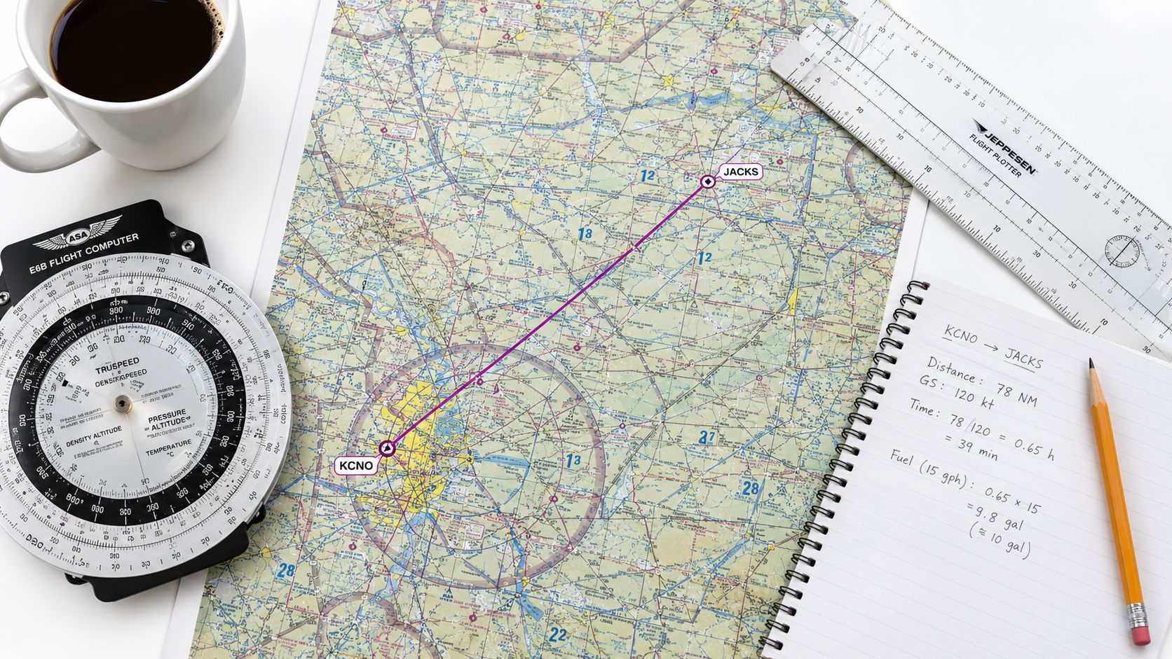
For a practice leg of 75 nautical miles at 110 knots, the pilot first marks or identifies the distance on the circular side. The E6B is then set so the computed speed aligns with the speed index or the appropriate rate reference. The inner time scale gives the elapsed time for the leg. The pilot should record the result in hours and minutes, not just as an unlabeled decimal.
Turn time into fuel
Fuel planning uses the same chain. The aircraft's POH provides the planned fuel-flow figure, and the E6B supplies the time relationship. Fuel required equals burn rate multiplied by time, while endurance equals usable fuel divided by burn rate (E6B fuel-planning method).
For example, with a planned burn of 8.5 gallons per hour, the pilot places the time value against the fuel-flow value and reads the gallons required. The result should be compared with the aircraft's POH guidance, planned taxi fuel, reserve policy, destination conditions, and the amount already aboard. The E6B does arithmetic, but it doesn't decide whether the planned fuel margin is operationally adequate.
A 15-knot headwind or tailwind swing can change both time and fuel. A headwind lowers groundspeed and increases time aloft, while a tailwind does the opposite. The correct response is to update the navigation log when the wind estimate changes rather than treating the original answer as fixed.
Use a second check before departure
The pilot should cross-check the computed time against the chart distance and groundspeed estimate. If a short leg produces an implausibly long time, the likely causes include a misplaced decimal, the wrong scale, or a speed value being read as distance.
A practical training plan can also include 20 minutes of reserve as an explicit planning exercise, then a final comparison with the FBO fuel order before engine start. Reserve planning must still follow the applicable operating rules, aircraft requirements, weather, and instructor guidance. The E6B confirms the arithmetic, not the complete go or no-go decision.
Working Out Density Altitude and Unit Conversions
Density altitude connects pressure altitude and temperature to aircraft performance. On a warm Chino afternoon, a student may calculate it once during training and then discover that the result changes the takeoff and climb discussion. The E6B provides a repeatable method, but the pilot still has to interpret what the result means for the aircraft.
For a practice example, use a field elevation of 650 feet, an altimeter setting of 29.85 inches of mercury, and an outside air temperature of 32°C. First determine pressure altitude. The common method uses the difference between 29.92 and the current altimeter setting, multiplied by 1,000 feet, then adds that adjustment to field elevation (density-altitude method).
Set the pressure altitude in the E6B's temperature and altitude window. Align the outside air temperature over that pressure altitude, then read density altitude from the curved scale. The pilot records the result next to expected takeoff-roll and climb-performance notes, then checks those notes against the aircraft's POH. A higher density altitude generally means the aircraft must be evaluated more carefully for available performance, but the POH remains the controlling reference for aircraft-specific planning.
Keep conversions separate from performance work
Conversion problems are easy to rush because they look less important than wind or fuel. They still create serious errors when a pilot confuses nautical miles with statute miles, or reads a Fahrenheit result as Celsius. The cleanest method is to write both the input and output units beside every answer.
| Conversion | Set On Scale | Read Result |
|---|---|---|
| Nautical miles to statute miles | Known distance and conversion index | Required distance unit |
| Knots to miles per hour | Airspeed value and speed conversion | Miles-per-hour value |
| Gallons to liters | Fuel quantity and volume conversion | Liters |
| Fahrenheit to Celsius | Temperature value and temperature conversion | Celsius |
A pilot working on true airspeed should keep the conversion step distinct from the wind step. The true airspeed calculation guide provides a related training reference, while the E6B gives the physical practice needed to recognize whether the final result is reasonable.
Using the Manual E6B Alongside a Modern Cockpit
The manual E6B works best beside electronic equipment, not in competition with it. A modern cockpit may calculate groundspeed, heading, estimated time en route, and fuel information quickly, but the pilot still needs a way to recognize whether the displayed answer fits the flight conditions.
The manual device is especially useful during preflight planning, training, and troubleshooting. It can continue working when a battery-powered device needs attention, an avionics display reboots, or a pilot wants an independent calculation. It also gives the pilot a magnetic and visual method for checking a heading or wind correction rather than relying on one display.

Know what each method does well
A manual E6B requires accurate marks, a steady hand, and familiarity with the scales. It also introduces rounding differences, so two pilots using different models may obtain slightly different answers. Those differences are normal when the inputs are approximate, but a large disagreement deserves investigation.
Electronic calculations are faster and easier to repeat. They can reduce the workload during a long cross-country, while the manual unit exposes the relationship between variables. Mental estimates can be faster still once the pilot has enough practice to recognize the expected range.
| Manual E6B | Electronic calculation |
|---|---|
| Doesn't depend on a battery | Produces results quickly |
| Shows the wind triangle physically | Repeats calculations efficiently |
| Builds ratio and estimation skills | Reduces scale-reading errors |
| Requires careful setup | Requires power and correct inputs |
A balanced workflow is simple. The pilot plans the cross-country manually first, verifies the numbers in the approved electronic equipment before departure, and returns to the E6B when a displayed result looks suspicious. Training resources comparing an electronic aviation computer with tablet-based planning can be found in this flight-planning comparison. The tool changes, but the pilot remains responsible for understanding the inputs and checking the output.
Practice Problems and a Pre-Checkride Checklist
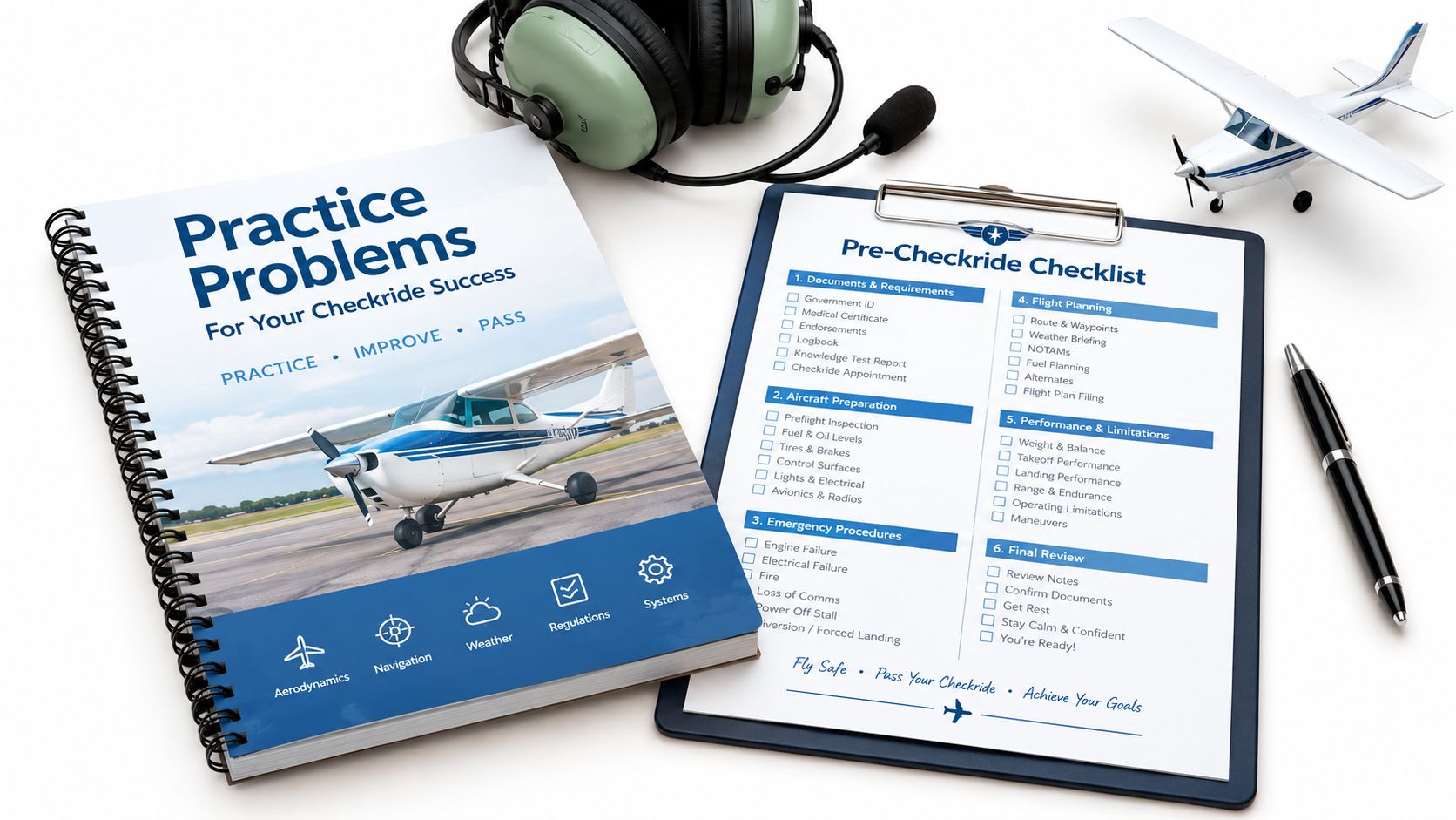
The best practice problems connect several calculations instead of asking for one isolated answer. Each exercise below uses stated inputs so the pilot can work the E6B, record the result, and explain the reasoning in a checkride-style conversation.
Three calculation drills
Problem one, complete a short navigation leg. Known values include a plotted course from KCNO to a practice area, a charted distance, wind information, true airspeed, and fuel flow. The unknowns are true airspeed if an indicated-airspeed correction is required, groundspeed, time en route, and fuel used. The answer should appear as a labeled navigation-log entry, with units beside every value.
Problem two, resolve a crosswind. Set a course, airspeed, and wind on the wind side. Read the wind correction angle, apply it in the correct direction, and calculate groundspeed. Then deliberately introduce a five-degree heading error and explain how that changes the expected track and estimated arrival time. The value of the exercise is not a perfect number. It is the ability to identify the operational consequence of a small setup or reading error.
Problem three, evaluate a warm-airfield departure. Use the KCNO practice inputs of field elevation, altimeter setting, and outside air temperature from the density-altitude example. Find density altitude, then compare the result with the POH takeoff-roll and climb-performance information. The pilot should be able to explain why the performance note matters before accepting the aircraft for departure.
Pre-checkride E6B checklist
- Plot the route: Confirm the course and distance before opening the E6B.
- Check wind information: Verify the age and applicability of the wind data.
- Set the true index: Start every wind problem from the correct reference.
- Label every mark: Identify course, airspeed, wind, and groundspeed.
- Check conversion direction: Confirm whether the scale is converting into or out of the selected unit.
- Sanity-check units: Read knots, nautical miles, gallons, hours, and temperatures aloud.
- Verify fuel reserve: Compare calculated fuel with aircraft requirements and the approved planning standard.
- Brief the maneuver: Connect the number to the next flight task, such as takeoff, climb, cruise, or descent.
A student who can explain each answer clearly is better prepared than one who can only produce a number. Continued preparation can include DuBois Aviation ground school support or a mock checkride focused on navigation, performance, and cockpit decision-making.
DuBois Aviation provides airplane and helicopter training, aircraft rental, ground instruction, and checkride preparation at Chino Airport. Pilots can visit DuBois Aviation to ask about course availability, navigation-planning practice, or a mock checkride that builds confidence with the E6B and modern cockpit tools.