
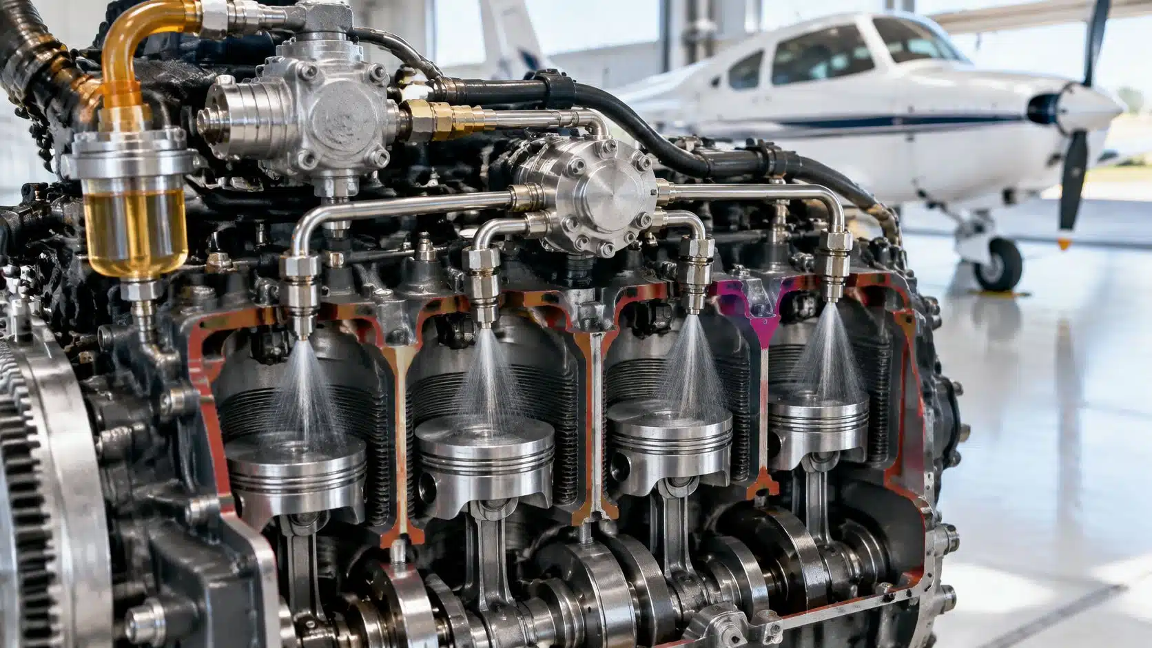
Aircraft fuel injection meters fuel according to the airflow entering the engine and delivers it through nozzles at each cylinder's intake port, instead of relying on a carburetor venturi to draw fuel into the air. In a conventional mechanically injected piston engine, the pilot still manages mixture, and the system needs adequate fuel pressure to work correctly.
If injection improves fuel delivery, why can an injected engine still run rough, lose power, or resist starting? The answer lies in the whole system, not just the nozzles. Pilots need to understand what supplies pressure, what meters fuel, and which cockpit procedure applies when either stops working as expected.
Table of Contents
- What Aircraft Fuel Injection Does and How It Differs from a Carburetor
- How Fuel Moves from the Tank to Each Cylinder
- Fuel Pressure Windows and Why They Matter
- Mixture Control, Leaning and Altitude Performance
- Icing and Fuel Injection Symptoms Pilots Should Recognize
- Fuel Quality, Contamination and Icing Inhibitor Handling
- Real-World Examples and Shutdown Errors in Light Aircraft
- Decide Whether Injection Training Fits Your Plan
- Frequently Asked Questions About Aircraft Fuel Injection
What Aircraft Fuel Injection Does and How It Differs from a Carburetor
A carburetor works somewhat like a straw: air moving through a narrowed passage creates a pressure drop that draws fuel into the airstream. Mechanical injection is more like a metered tap, releasing fuel in relation to the air moving through the engine.
That analogy has a limit. An injected engine still uses pressure differences to measure airflow, but it doesn't use a carburetor's fuel-discharge arrangement. Fuel travels separately to individual nozzles near the cylinders' intake ports.
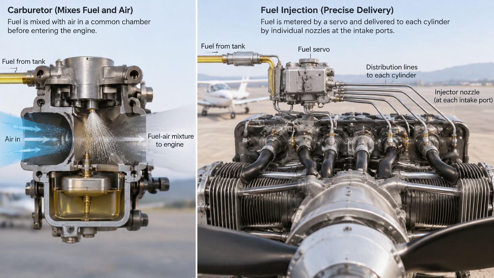
Wartime development illustrates why that distinction mattered. During 1944 testing of the Wright R-3350 used on Boeing B-29 bombers, engineers addressed mixture and cooling problems with fuel injection and redesigned cylinder airflow, achieving an 18% increase in fuel efficiency, according to NASA's account of its wartime altitude-wind-tunnel work. That was a combined engineering improvement, not evidence that adding injection alone produces the same gain in a light airplane.
Carburetor versus fuel injection at a glance
| Feature | Carburetor | Fuel injection |
|---|---|---|
| Fuel metering | Venturi pressure drop draws fuel into the airstream | Fuel flow set against a pressure signal from incoming air |
| Cylinder distribution | Can vary from cylinder to cylinder | Flow divider and individual nozzles meter fuel to each cylinder |
| Carburetor icing exposure | Significant when temperature and humidity conditions allow vaporization cooling | Greatly reduced, though induction icing is still possible |
| Starting technique | Primer and throttle procedure, with risk of flooding | Mixture technique and procedure set by the aircraft manual |
| Main failure concern | Icing, float or jet issues | Fuel pressure, nozzle cleanliness, pump and regulator condition |
What changes for the pilot
The practical differences are more controlled cylinder distribution, lower carburetor-icing exposure, and greater attention to pressure and clean metering components. More controlled distribution doesn't mean every cylinder always receives an identical mixture.
The aircraft's approved flight manual or pilot's operating handbook, abbreviated AFM or POH, identifies the installed system and its procedures. Engine naming conventions, familiar cockpit controls, or experience in a similar airplane aren't substitutes for checking that document.
Practical rule: Fuel injection changes the pilot's procedures. It doesn't remove the need for them.
Starting, mixture management, and alternate-air operation deserve particular attention during a rental checkout or aircraft transition. Injection doesn't eliminate induction icing, and it isn't an automatic replacement for checklist discipline.
How Fuel Moves from the Tank to Each Cylinder
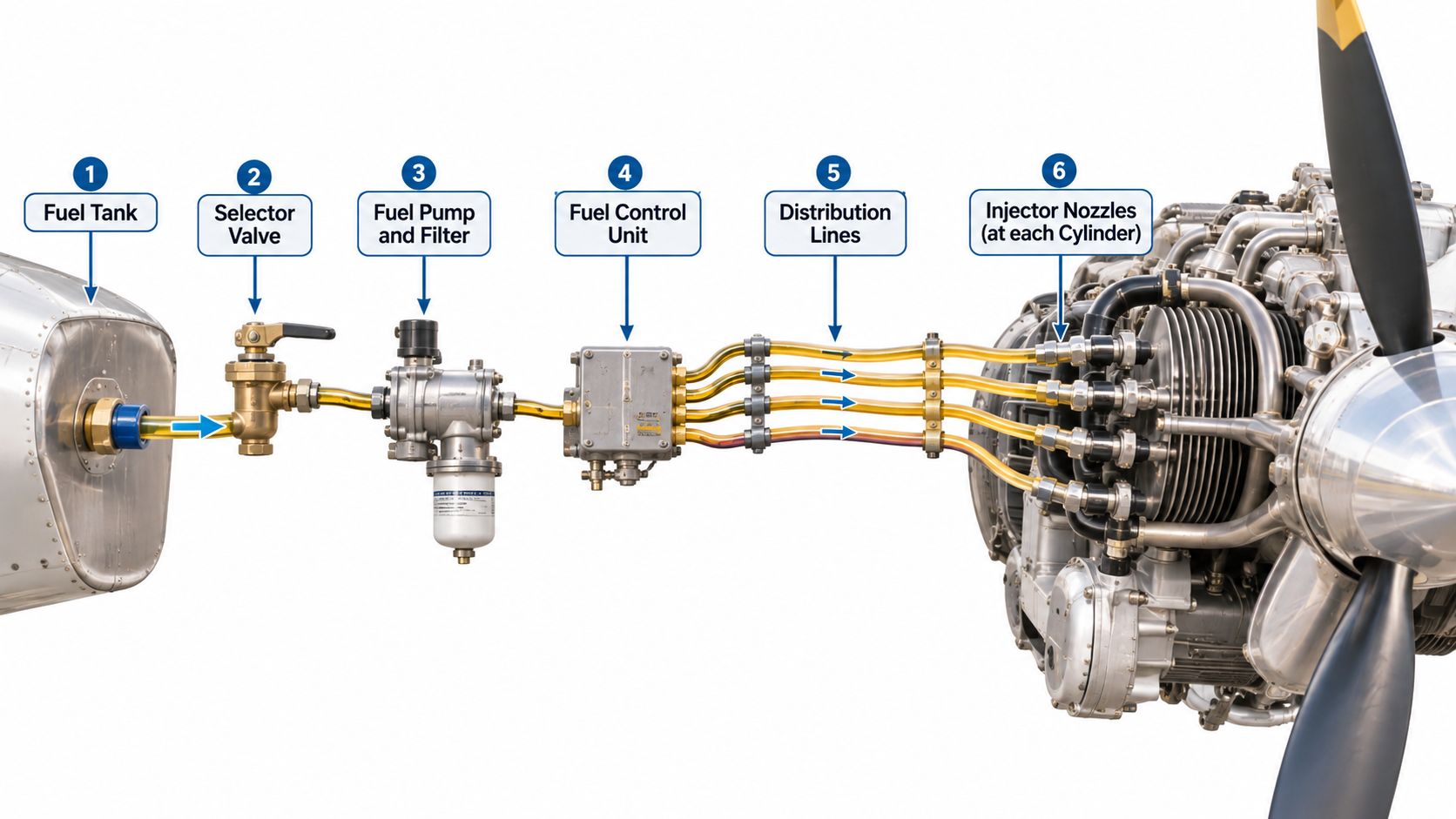
Following the fuel makes the system easier to understand. The FAA's powerplant maintenance handbook describes mechanically controlled injection through its airflow, regulator, and fuel-metering sections, with metered fuel routed through a flow divider to individual nozzles.
The fuel path in operating order
The following is a functional walkthrough, not a universal plumbing diagram. Pump and filter locations, bypass arrangements, and backup capabilities must be checked against the particular aircraft.
- Tank outlet and selector. These supply fuel from the selected tank or tanks. An incorrect selection or interrupted supply can starve an otherwise serviceable injection system.
- Fuel pumps. The engine-driven pump establishes supply pressure, while an electric boost pump commonly supports priming or backup functions. Its approved use and capabilities are installation-specific.
- Filter or screen. Filtration intercepts contaminants before sensitive metering components. A restriction can reduce delivery, while contamination that passes through can affect downstream parts.
- Airflow-sensing regulator and metering section. These relate fuel delivery to induction airflow. Incorrect regulation can produce an unsuitable mixture even when fuel remains available upstream.
- Flow divider. This routes metered fuel into the individual cylinder lines. Distribution problems can contribute to uneven operation.
- Injector nozzles. These atomize and discharge fuel at each intake port. Restricted passages can disturb a cylinder's fuel delivery.
Think of the regulator as a tap linked to airflow through a pipe. As airflow increases, the system increases fuel flow approximately in proportion, within its calibrated operating range.
Fuel injection components, functions and warning signs
| Component | Main job | Typical warning sign |
|---|---|---|
| Engine-driven fuel pump | Establishes supply pressure | Pressure drop at high power or fuel starvation |
| Electric boost pump | Provides approved backup and priming pressure | No expected pressure response when switched on |
| Fuel filter or screen | Removes contamination before metering | Delivery restriction, or contamination found during inspection |
| Airflow-sensing regulator or metering unit | Sets fuel flow relative to airflow | Unexpected rich or lean operation and roughness |
| Flow divider | Splits metered fuel among cylinder lines | Uneven cylinder temperatures or cylinder-specific roughness |
| Injector nozzles | Atomize and deliver fuel at each intake port | Rough running on one or more cylinders, reduced power |
| Mixture control | Adjusts fuel-to-air ratio toward idle cutoff | Sticking or misrigging that prevents proper adjustment |
These are clues, not diagnoses. An upstream supply problem can resemble a downstream nozzle fault, so maintenance personnel must evaluate the complete system rather than clean a nozzle by assumption.
Electronic injection is a related but different architecture that uses sensors and an engine control unit. For a mechanical system, the pilot should be able to name where pressure comes from, what sets flow, and where fuel enters the induction air.
Fuel Pressure Windows and Why They Matter
A fuel pressure gauge gives you one number, but that number only becomes useful inside a window. A bicycle tire shows the idea: the sidewall prints a pressure range because too little pressure lets the tire squirm and too much strains the rim. An injected engine works the same way. The approved fuel pressure range belongs to the exact engine and aircraft installation, and it assumes you read the gauge at the specified location.
That location matters. A reading taken at the injector inlet can differ from a reading taken at the pump outlet, so a number copied from another airplane has no authority in yours. The same logic applies across engine families. Several Lycoming IO-320 models and the IO-360-M1A each publish their own injector inlet limits, and those limits stay with the engine model and installation. Use the manual that covers your engine, and keep the chart with the engine model.
| Engine reference | Limit to confirm | What it means in practice |
|---|---|---|
| Lycoming IO-320, several models | Minimum and maximum injector inlet pressure in the model-specific manual | Use the value for the exact model and the specified port |
| Lycoming IO-360-M1A | Minimum and maximum injector inlet pressure in the model-specific manual | Apply this engine's chart and keep it with the engine model |
Below the approved window, inadequate supply can reduce delivery and produce an excessively lean condition, roughness, or power loss. Above the window, an abnormal reading can point to a regulator, pump, restriction, or metering problem. Pilots get into trouble when they treat the gauge as a pass or fail number without checking the power setting and the measurement point.
A climb indication needs context
Consider a pilot who sees fuel pressure moving toward the bottom of the approved range during climb. The pilot needs to evaluate the indication against the aircraft's checklist, engine behavior, fuel flow, and other available instruments, rather than treating a needle inside a colored arc as proof that nothing is wrong.
Fuel pressure and manifold pressure answer different questions. The first describes the fuel supply; the second describes the air load going into the engine. The distinction matters when you discuss power settings and troubleshoot an indication, and this explanation of manifold pressure and engine operation helps separate the air side from the fuel side.
Use the boost pump only when the aircraft's procedure calls for it. The pump can restore pressure in some configurations, and in others it can mask the cause or create a new indication.
For fleet operation, useful maintenance practices include recording pressure and flow under specified conditions, investigating unexplained roughness before routine redispatch, and checking indications against the correct installation documentation. When pressure moves, write down the reading, the power setting, the altitude, and what the engine was doing at that moment. That record gives a mechanic or instructor the context to separate a gauge quirk from a supply problem.
Mixture Control, Leaning and Altitude Performance
The throttle primarily controls airflow and engine power, with the metering system responding through fuel delivery. The mixture control changes the proportion of fuel relative to air.
A recipe offers a useful analogy. Throttle resembles changing how much food is served; mixture resembles changing the seasoning concentration in each portion. Increasing the quantity and changing the proportion aren't the same adjustment.
The FAA's induction-system guidance identifies mixture as the most influential temperature control at a given cruise power. That's why mixture movement can strongly affect exhaust-gas temperature or, where installed and applicable, turbine-inlet temperature.
Why altitude still requires pilot attention
As air density falls with altitude, an improperly adjusted fuel schedule can leave the engine excessively rich. The engine may consume unnecessary fuel and operate less efficiently even though its injection components are functioning.
Airflow-related metering doesn't automatically mean complete altitude compensation. A student shouldn't assume that an engine with injector nozzles manages its own mixture.
The cockpit task is to use the approved power and leaning procedure, supported by the instruments installed. An airplane with a basic temperature indicator and an airplane with individual-cylinder monitoring may require different instrument interpretation.
A deliberate leaning sequence
- Establish the approved power setting. The POH determines whether leaning is appropriate for the operating condition and how power should be set.
- Move the mixture gradually. Where the manual calls for leaning from full rich, the pilot should lean slowly while watching the specified instrument and engine response.
- Stop at the approved setting. The selected power, temperature limits, and manufacturer's procedure determine the endpoint.
- Recheck after a change. A new altitude or power setting may require another mixture adjustment.
This is a learning framework, not an aircraft-specific checklist. It doesn't establish a universal exhaust-temperature target, cylinder-head-temperature limit, or rich-of-peak versus lean-of-peak procedure.
Leaning by feel alone is a common mistake. Smooth operation is useful information, but it doesn't establish that the engine is operating at the manufacturer's recommended mixture for the selected power.
During transition training, an instructor should connect each mixture adjustment to a reason: starting, climb performance, cruise operation, or shutdown. Students then learn a system instead of memorizing an unexplained control position.
Icing and Fuel Injection Symptoms Pilots Should Recognize
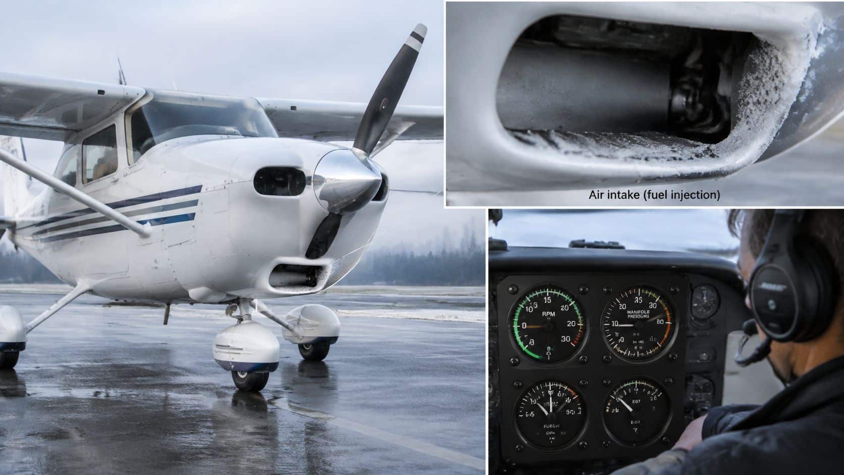
Fuel injection greatly reduces carburetor icing because it avoids the carburetor arrangement where fuel vaporization and pressure reduction produce substantial cooling. Ice can still obstruct the engine air intake, however, and cause roughness or power loss.
The FAA's induction-icing advisory circular describes alternate-air arrangements commonly used in injected airplanes, including automatic sources with manual backup. The installed design determines whether the pilot has a control to select and what the checklist requires.
Match the symptom to the approved response
The FAA's fuel-system safety discussion distinguishes plugged nozzles, excessive pressure or flow, pressure loss, and engine-driven pump failure. Those conditions don't all call for the same control movement.
The actions below apply only as directed by the aircraft's AFM or POH. A symptom can have several causes, and an in-flight checklist isn't permission to perform maintenance troubleshooting in the cockpit.
Fuel injection symptoms, likely causes and responses
| Symptom | Likely system area | In-flight response | Maintenance follow-up |
|---|---|---|---|
| Fuel pressure drop or fluctuation | Pump, filter, leak or regulator | Boost pump and power reduction as directed by the AFM | Inspect pump, filter and lines before next flight |
| High fuel pressure or flow | Regulator or restriction | Reduce power and lean only as appropriate under the AFM | Check regulator, restrictions and metering calibration |
| Roughness or power loss with suspected icing | Induction icing at the air intake | Apply alternate air as the AFM directs | Inspect intake and alternate-air operation |
| Roughness on one or more cylinders | Plugged nozzle or flow-divider problem among possible causes | Reduce power as directed; avoid unnecessary high power | Qualified inspection and nozzle servicing where indicated |
| Engine-driven pump failure | Pump | Boost pump, mixture and power according to the AFM | Inspect before further flight |
Selecting carburetor heat isn't a universal response to an injected engine's roughness. The pilot must identify the installed alternate-air system before flight and distinguish an intake-air problem from a fuel-delivery problem.
Understanding icing conditions and their operational implications also helps prevent the mistaken assumption that an injected engine removes icing from the flight-planning discussion.
After landing, the report should describe power setting, altitude, indications, and the effect of checklist actions. Injector cleaning alone won't correct contaminated supply fuel, a failing pump, or incorrect additive handling.
Fuel Quality, Contamination and Icing Inhibitor Handling
What does a clean fuel sample prove? It proves what came out of one drain point at one moment. In a pressure-fed injection system, water or debris that passes the filter can still disturb the flow divider or a nozzle, and the pilot notices roughness, a lean miss, or a power drop that may first look like an engine problem. Before the first flight, draw fuel from each drain point named in the POH or AFM, check it for water and sediment with the specified test, and record the result.
The FAA's aviation-fuel handling guidance.pdf) calls for storage-tank and fueling-truck fuel to be checked at least daily for quality and evidence of water or contaminants, and it sets a minimum DiEGME concentration of 0.04% by volume for fuel-system icing-inhibitor use. Apply that minimum when the aircraft's approved fuel specification calls for DiEGME.
Treat the inhibitor as a measured fuel-system product
An icing inhibitor has a required concentration and a mixing procedure. Pouring it in as a concentrated slug can damage components, create deposits, and contribute to power loss. Keep piston avgas additive practices separate from turbine-fuel procedures. An injected engine or a cold forecast does not by itself make an inhibitor appropriate. The aircraft limitations, approved fuel specification, and current handling guidance determine whether an additive is permitted or required.
Maintenance boundary: A clear sample verifies the drain point. Screens, filters, the flow divider, and nozzles need inspection under the maintenance manual.
A practical contamination checklist
- Sample every specified point. Draw fuel from each drain point named in the POH or AFM into a clear sampler. Check for water, sediment, and the correct fuel, then record the result.
- Confirm the supplier's daily checks. Ask the fueler to confirm the truck and storage-tank quality check and water test for that day, and note the supplier and date on the receipt.
- Inspect filtration on schedule. During maintenance, have qualified personnel open and inspect fuel screens, filters, and sump drains using the maintenance manual.
- Match the additive to the approval. Use only the product named in the approved fuel specification, measure the concentration stated for that use, and mix it by the manufacturer's procedure before fueling.
- Resolve contamination before flight. Water or sediment in a sample requires stopping, finding the source, and repeating the sample.
A restriction may disappear after nozzle cleaning while the contamination source remains upstream. Effective fuel-management practices therefore include fuel identity, condition, handling, and reporting alongside quantity planning.
Real-World Examples and Shutdown Errors in Light Aircraft
A starting habit learned in a carbureted airplane can become the wrong habit in an injected airplane. Familiar control colors don't guarantee familiar priming, boost-pump, or mixture procedures.
These situations are training scenarios, not accounts of actual flights. Each illustrates why a pilot needs to connect the control movement with the system it affects.
Familiar situations with different decisions
- Rapid leaning during climb. A pilot moves the mixture too far and the engine becomes rough. The appropriate response is to correct the mixture under the POH procedure, not continue leaning in search of smoothness.
- Roughness interpreted automatically as carburetor ice. A pilot reaches for a remembered carburetor-heat control even though the aircraft uses alternate air. Ground familiarization should establish the correct control and procedure before that confusion occurs.
- A transferred starting technique. A pilot uses a carbureted airplane's mixture and priming sequence in an injected airplane. The manufacturer's cold-start, hot-start, or flooded-start procedure must replace the borrowed habit.
Common errors include leaning by feel alone, confusing boost-pump and selector functions, transferring starting habits, and learning control locations in flight. These are procedural problems that system knowledge can help prevent.
Securing fuel is different from switching off ignition
The FAA's Airplane Flying Handbook describes securing an engine, unless the AFM or POH specifies otherwise, by placing the mixture in idle cutoff, switching off the electric boost pump, and positioning the fuel selector as required. Ignition and the alternator or generator are secured as part of the complete procedure.
For an engine fire, the FAA's general guidance identifies shutting off the fuel supply, including mixture to idle cutoff and the fuel-selector shutoff valve to OFF, as the first step unless the manufacturer directs otherwise. That general description isn't a replacement for the aircraft's fire checklist, which depends on the situation and installation.
A normal shutdown checklist and an emergency engine-securing checklist shouldn't be treated as interchangeable. Before flight, pilots should practice identifying mixture, boost-pump, selector, and alternate-air controls on the ground, with an instructor supervising any control operation.
Decide Whether Injection Training Fits Your Plan
Start with the airplane you will fly. The useful goal is narrow: identify the installed system, explain its main components, recognize abnormal indications, and perform the approved procedures for that installation. That goal shifts with the mission. Private, instrument, and multi-engine training each place different demands on system knowledge.
DuBois Aviation offers one-on-one airplane and helicopter instruction at Chino Airport, from discovery flights through advanced ratings. Discovery-flight customers choose an airplane or helicopter according to their interests, goals, and scheduling availability. The enrollment options include Private Pilot – Airplane, Instrument Rating – Airplane, Commercial Pilot – Airplane, Flight Instructor Training, Multi-Engine Training, Helicopter Training, and Other. DuBois Aviation operates eleven aircraft, including six Piper Cherokees, a Cessna 150, a Mooney Mark-20B, a Piper Apache, a Robinson R-22, and an Enstrom F-28, so the aircraft assigned to your airplane course determines which fuel system you will learn.
For a prospective student, choose the training airplane for the whole plan: schedule, instructor fit, aircraft availability, and the ratings you intend to pursue. Then add the fuel system to the checkout list. For a certificated renter, an unfamiliar injection system is a clear reason to request focused ground instruction and a thorough checkout.
Match the lesson to the aircraft
A private pilot student needs procedures that work consistently on cold starts, hot starts, and leaning during climb. An instrument student needs the same procedures plus the ability to recognize a fuel-pressure or power problem without losing scan or aircraft control. A multi-engine transition adds another reason to distinguish fuel supply, engine securing, and checklist priorities. Instructor candidates should be able to explain those distinctions clearly instead of teaching one universal sequence across different installations.
Questions before booking
- Which aircraft will I fly? Ask which aircraft in the fleet your course uses before you book, then review that type's manual. Fuel-system hardware and starting procedures vary by installation.
- Where is the approved manual? Review starting, leaning, fuel-pump, and alternate-air procedures before operating an unfamiliar airplane.
- How will procedures be practiced? Ask how ground familiarization and flight exercises will build mixture management and emergency-control recognition.
When you request training information, include your current certificate, intended rating, and any aircraft-transition concerns. That gives the school a concrete basis for discussing course availability and the preparation that fits your plan.
Frequently Asked Questions About Aircraft Fuel Injection
Which instrument shows an injected engine is running over-rich?
Fuel flow. The metering unit sends fuel forward according to the air it senses, so the flow gauge reports what was delivered, not what the engine managed to burn. When flow sits well above the expected figure for a power setting while exhaust gas temperature falls and the engine runs rough, the mixture is too rich for the conditions. Lean toward the setting the manual specifies and watch the two indications come back together.
Does a fuel-injected engine need carburetor heat?
An injected engine has no carburetor, so there is no throttle-body venturi to ice. What it does have is an induction-air inlet that ice or debris can restrict, which is why many installations provide an alternate air source, either automatic or selected by the pilot. Carburetor heat and alternate air solve a related problem by different routes: one warms air before the venturi, the other gives the engine a second door to breathe through. Know which one your airplane has before you need it.
Does the electric boost pump stay on all flight?
Usually not. Many procedures call for the pump on for takeoff, landing, and any change of altitude or power where a supply interruption would be costly, then off in cruise where the engine-driven pump carries the load. Leave it running when the manual says off and an over-rich or high-pressure condition can follow. Forget it during a critical phase and a failing engine pump has nothing behind it. The switch position belongs on your before-takeoff flow, not on memory.
Is electronic fuel injection the same as mechanical injection?
No, and the difference changes what you monitor. Mechanical systems rely on pressure relationships, a metering unit, and lines that distribute fuel downstream to each cylinder. Electronic systems read sensors, calculate a delivery value in an engine control unit, and fire injectors to match. Starting routines, backup modes, and the indications you trust in flight are specific to each design, so treat a new type as new. The manual for the installed system is the final authority.
Why does an injected engine idle rough when leaned on the ground?
At idle, total fuel flow is small and the share reaching each cylinder is uneven, so a lean setting that would be smooth at cruise can leave one cylinder contributing little. That stumble is a mixture signal more often than a fault. Set idle mixture per the procedure, expect some roughness at a lean idle, and enrich if the engine will not keep running.
DuBois Aviation offers one-on-one airplane and helicopter instruction at Chino Airport, with preparation grounded in checklists, aircraft limitations, and proficiency. For help connecting fuel-system knowledge to an aircraft transition or training goal, visit DuBois Aviation and request training information or ask about course availability.