
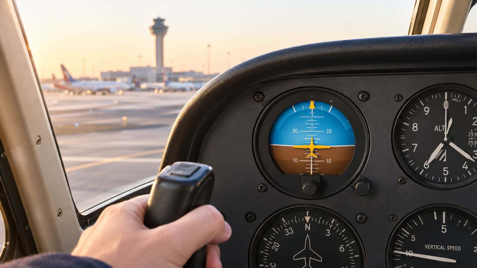
A student turning base to final at Chino Airport can lose the outside horizon in haze, darkness, or a cloud layer within seconds. An aircraft attitude indicator provides the primary direct display of pitch and bank against an artificial horizon, but it isn't an unquestionable picture of reality. It is a gyroscopic reference that can precess, lose power, or be misread, so safe instrument flying depends on using it with a disciplined cross-check.
Table of Contents
- What an Aircraft Attitude Indicator Does
- The Brief History of the Attitude Indicator
- How the Attitude Indicator Works
- Comparing Vacuum, Electric, and Glass Attitude Indicators
- Reading the Attitude Indicator in Flight
- How the Attitude Indicator Can Fail or Mislead
- Partial Panel Scan and Preflight Checks
- Training Tips, Common Mistakes, and Pilot FAQs
What an Aircraft Attitude Indicator Does
At Chino, a student may roll onto final while haze, darkness, or an instrument approach hides the outside horizon. The aircraft attitude indicator, or AI, supplies a miniature horizon that shows whether the airplane is nose-up or nose-down and banked left or right. A small aircraft symbol relates to a horizon bar, giving the pilot a reference when the true horizon disappears. The FAA Airplane Flying Handbook identifies the AI as the instrument that directly displays pitch attitude. Airspeed, altitude, vertical speed, and heading add supporting evidence during the scan.
The AI is a starting reference, not a verdict. At a busy towered airport such as KCNO, a pilot may copy a clearance, watch for traffic, adjust power, and prepare for an approach while the outside picture fades. The instrument can help establish control, while the remaining instruments test whether its picture still makes sense.

The six instruments work as a system
The traditional basic six includes:
- Airspeed indicator, showing speed through the air.
- Attitude indicator, showing direct pitch and bank.
- Altimeter, showing altitude according to the selected pressure setting.
- Vertical-speed indicator, showing the trend and rate of climb or descent.
- Turn coordinator, showing turn rate and coordination.
- Heading indicator, showing the aircraft's heading reference.
The AI sits at the center because pitch and bank changes influence nearly every other indication. A nose-low attitude can bring rising airspeed and falling altitude. A bank can change heading and, if left uncorrected, lead to an unintended descent. Read the indications together. Chasing one needle can hide the attitude that caused the problem.
A disciplined pilot also remembers that the AI is a fallible gyroscopic instrument. Power loss, precession, or an inaccurate display can turn its apparent horizon into a misleading reference. Cross-checking is therefore part of controlling the airplane, not an optional check after the fact.
Aircraft construction and component reliability matter for the same reason. Readers seeking broader context on how aviation components are produced and maintained can review American Additive Manufacturing's aviation industry services, which describes manufacturing support in the aviation sector.
In training, the two questions that decide everything are how the instrument builds its artificial horizon and what a pilot does the day that horizon lies.
The Brief History of the Attitude Indicator
Before a reliable artificial horizon, pilots depended heavily on outside visual references. That method breaks down in fog, clouds, darkness, and haze because human senses can't reliably detect gradual changes in pitch or bank without a visible horizon.
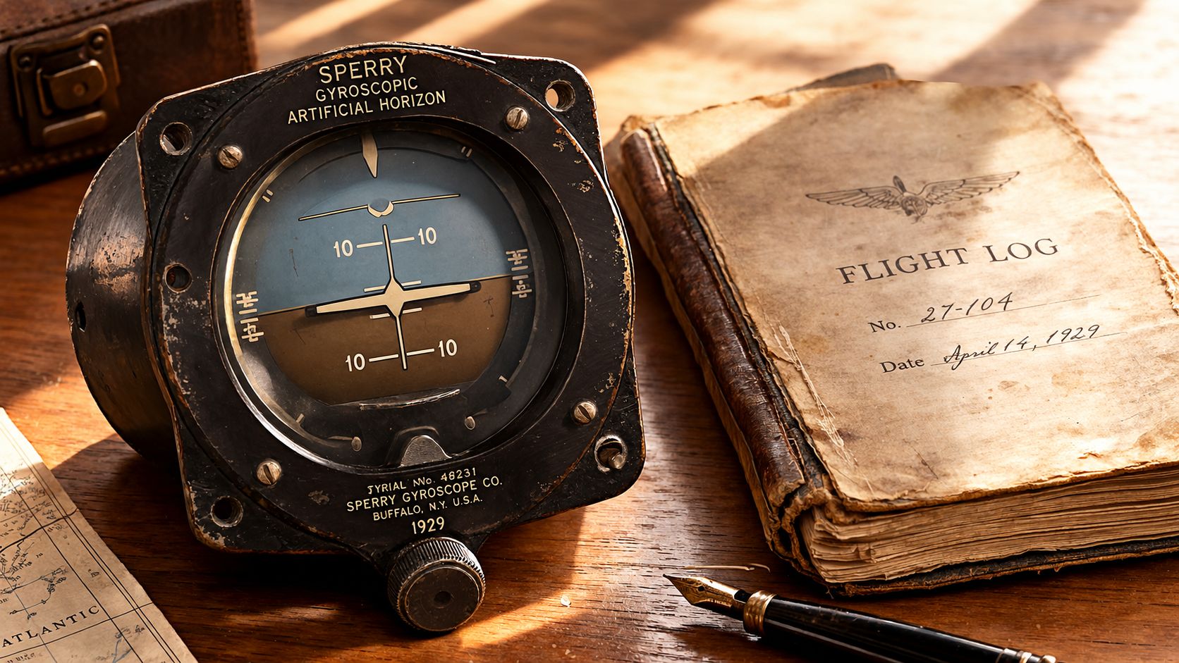
On September 24, 1929, U.S. Army pilots James “Jimmy” Doolittle and Benjamin Kelsey completed a pioneering 15-mile flight in dense fog using Sperry instruments, including an attitude indicator that displayed an artificial horizon when the natural horizon was invisible (Lockheed Martin's history of the Sperry artificial horizon). The flight demonstrated that pilots could take off, maintain controlled flight, and land by reference to instruments rather than outside visual cues.
Why the original idea still matters
The early Sperry artificial horizon used a rapidly spinning gyro as a stable spatial reference. The display then showed the aircraft's pitch and bank relative to that reference. The design addressed a fundamental human-factors problem, a pilot can feel movement without accurately identifying the aircraft's actual attitude.
That principle carried into the traditional basic six used in training airplanes. A student in a Piper Archer, Cessna trainer, or helicopter cockpit still needs the same fundamental skill: controlling attitude by instruments when the outside horizon isn't available. Electronic displays have replaced many mechanical gauges, but they haven't removed the need to understand pitch, bank, scan, and failure recognition.
The history also explains why the AI is not just a painted picture. Its reference depends on gyroscopic behavior, power, bearings, erection mechanisms, and the pilot's interpretation. Understanding rigidity and precession is therefore more useful than memorizing only the colors on the face of the instrument.
How the Attitude Indicator Works
At Chino, the outside horizon can disappear in seconds after departure. Your first reference is the attitude indicator, but treat its picture as a gyro-generated estimate, not as an unquestionable view through the windshield.
The miniature airplane represents the aircraft. The horizon bar represents the instrument's artificial horizon. If the two symbols show wings level and a modest pitch attitude, use that information to establish control, then confirm it with the rest of the panel.
Inside a conventional AI, a rapidly spinning rotor resists changes to its plane of rotation. This property is called gyroscopic rigidity. The aircraft moves around the stabilized gyro, and linkages convert that relative movement into pitch and bank on the display.
The mechanical chain
The system works through several connected steps:
- Rotor speed creates stability. A vacuum or pressure system, or an electric motor, spins the gyro.
- The gyro resists movement. Its stable reference lets the instrument show the aircraft's attitude relative to the rotor.
- Forces produce precession. Friction, bearing wear, contamination, and vibration can gradually shift the gyro from its intended reference.
- The erection system corrects drift. Pendulous vanes and airflow apply corrections that return the reference toward vertical.
- The display shows the result. If drift exceeds the correction system's ability, the horizon bar can become slowly false.
Precession is where instrument students often get caught. The AI does not know the outside horizon. It only reports the relationship between the airplane, the gyro, and the correction mechanism. A false horizon may develop gradually, remain visually convincing, and lead the pilot to make larger control errors while trying to correct an attitude that does not exist.
The practical interpretation
The FAA describes the AI as a direct pitch reference, while its guidance also places that indication within a supporting instrument scan (FAA Airplane Flying Handbook). That pairing matters because the display can be wrong even when it looks normal.
Practical rule: Use the attitude indicator to set an attitude, then verify the airplane's performance.
Compare the AI with airspeed, altitude, vertical speed, heading, and turn and slip indications. If the AI shows wings level while the turn coordinator indicates a sustained turn and the heading changes, believe the disagreement before the picture. Reduce control inputs, identify which references agree, and continue the scan rather than chasing a single instrument.
Comparing Vacuum, Electric, and Glass Attitude Indicators
A renter who moves from a vacuum-driven Piper Cherokee to an electrically equipped trainer or glass cockpit may see the same basic horizon picture, but the instrument producing it may depend on very different systems. Treat the first flight in the new panel as a systems briefing, not just a familiarity lap. Before leaving the ramp, identify the power source, failure indications, and standby attitude reference.
| Indicator Type | Power Source | Pilot Monitors | Typical Failure Signature |
|---|---|---|---|
| Vacuum-driven mechanical AI | Engine-driven vacuum or pressure system | Suction or pressure gauge, warning flags, horizon behavior | Low system indication, sluggish movement, precession, or a slowly false horizon |
| Electrically driven mechanical AI | Aircraft electrical system | Electrical status, instrument flags, display response | Electrical failure, loss of indication, flag, or abnormal gyro behavior |
| Electronic attitude display | Independent electronic power and attitude-reference components | Power status, annunciations, system messages, related displays | Invalid attitude data, flags, frozen or disagreeing display, or loss of supporting reference |
Vacuum systems
In a legacy airplane, engine-driven suction spins the gyro. As suction drops below the normal operating range, rotor speed decreases, and the instrument becomes more vulnerable to friction and disturbance. The FAA Human Factors Handbook warns that low vacuum can make attitude and heading indicators unreliable.
Keep the vacuum gauge in the scan during instrument conditions. It is an early clue, not a maintenance detail to ignore. A developing failure may leave the attitude indicator looking reasonable while its accuracy slowly worsens. A pilot who waits for an obvious flag may already be correcting from a bad reference.
Electric and glass systems
An electrically driven mechanical attitude indicator avoids dependence on an engine-driven vacuum system, but it still requires a working electrical supply and functioning internal components. A glass display replaces the spinning mechanical gyro with electronic attitude-reference components, yet it remains dependent on power, sensors, data paths, and the display itself.
The useful question is not which category deserves automatic trust. Ask whether the attitude picture agrees with independent indications, where the failure annunciations appear, and what approved procedure applies if that source becomes unavailable. At a busy towered field, that knowledge matters before a distraction, clearance change, or partial-panel workload arrives.
A renter transitioning from a vacuum-driven Cherokee to a glass trainer should review DuBois Aviation's glass cockpit and steam-gauge training information and brief the new panel on the ground. Locate the failure flags, confirm the standby attitude source, and know how the scan changes before the wheels leave the ground. The attitude indicator is a helpful reference, not an authority.
Reading the Attitude Indicator in Flight
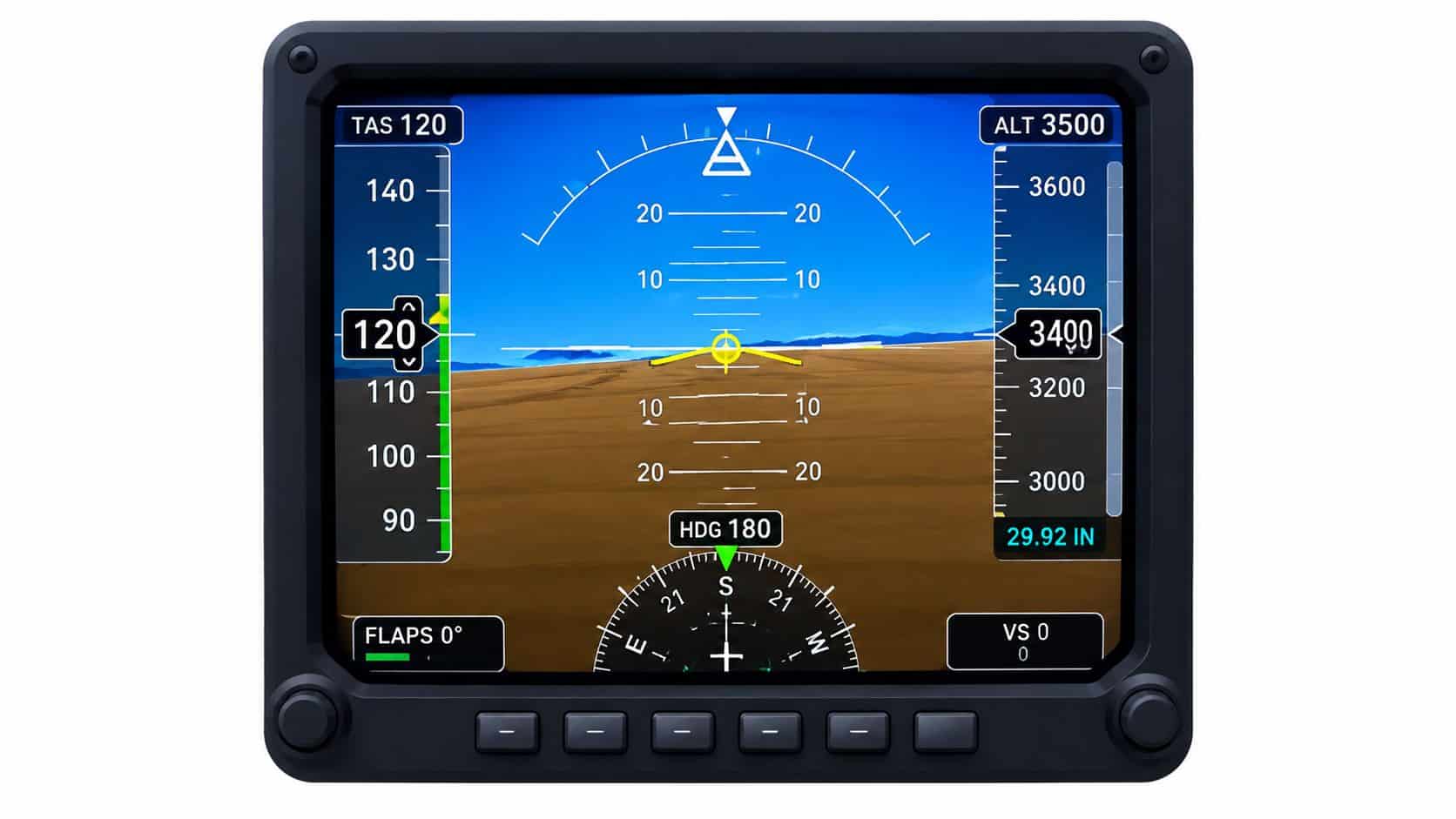
At Chino, a clearance change, radio call, or runway departure can interrupt your scan quickly. Keep the attitude indicator useful by treating it as a measured reference, not an unquestionable picture. Describe what it shows in approximate pitch and bank, then verify the airplane's response with independent instruments.
FAA guidance specifies pitch markings in increments of 5 degrees or less, extending from approximately 20 degrees nose-up through 40 degrees nose-down. It also specifies bank references for wings level and 10, 20, 30, and 60 degrees on both sides, with a 45-degree reference also permitted (FAA Advisory Circular AC 61-136A).
Use the reference grid
In straight-and-level flight, the miniature airplane should show the planned pitch attitude, with the wings aligned to the wings-level reference. Use the altimeter, vertical-speed indicator, airspeed indicator, and heading indicator to confirm altitude, speed, and direction. The AI sets the attitude picture. The other instruments check its result.
In a climb, set the pitch attitude shown by the AI, then watch airspeed and vertical speed. If the nose rises while airspeed falls more than expected, avoid chasing one instrument with abrupt control movements. Power, pitch, trim, and aircraft configuration all influence the outcome.
During a descent, apply the same process in reverse. Select the required attitude, then verify airspeed, altitude trend, and vertical speed. A nose-low indication does not by itself establish the desired descent rate. A nose-high indication does not prove that climb performance is adequate.
Bank and turn rate
In a coordinated standard-rate turn, the attitude indicator shows bank while the turn coordinator supplies the rate reference. FAA guidance uses 3 degrees per second for a standard-rate turn. Monitor the ball, heading trend, altitude, and airspeed as well. A bank picture without those checks is only part of the control problem.
Use a short callout to keep the scan organized:
- Pitch: State the approximate nose attitude.
- Bank: State the direction and approximate bank angle.
- Performance: Confirm airspeed, altitude trend, and heading.
- Coordination: Check turn rate and slip or skid indication.
This discipline makes the AI a control reference that must earn your confidence through agreement with the rest of the panel.
How the Attitude Indicator Can Fail or Mislead
At a busy towered field, a pilot may glance at the AI during a turn, accept its picture, and make a confident correction. If the instrument is failing, that correction can move the airplane farther from the intended attitude. The AI is a gyroscopic reference, not an authority. Its indication earns trust by agreeing with the rest of the panel.
An FAA study tested 41 instrument-rated general-aviation pilots. Among the Bonanza pilots, 25 percent could not maintain control after unannounced attitude-indicator failures. 30 minutes of partial-panel simulator preparation reduced average failure-recognition time from 7.6 minutes to 4.9 minutes (FAA study of attitude and heading instrument failures). The study's practical message for a student is clear: failure recognition is a trained skill with a measurable payoff, and partial-panel preparation improves how quickly the problem is identified.
Three ways the information can become unsafe
Power loss can reduce rotor speed in a vacuum-driven instrument. As the gyro slows, friction and outside forces create more precession, and the horizon can drift farther from reality. A low suction indication may therefore warn that the attitude display deserves less trust.
Erection or mechanical problems can produce a slowly false horizon. The display may look normal enough to invite reliance, unlike a blank screen. Compare it with the turn coordinator, airspeed, altitude, vertical speed, and heading. Agreement across independent indications provides a stronger basis for control.
Pilot-side errors can occur while the AI itself works normally. Fixation narrows the scan. A pilot may stare at the attitude picture, miss a changing airspeed, overlook heading drift, or make an input that increases the upset.
Acceleration and deceleration can also distort interpretation. A nose-low or nose-high indication may reflect a change in speed rather than a true descent or climb. The display shows one part of the aircraft's state, so recovery slogans such as “blue over brown” cannot replace a full instrument cross-check.
Spatial disorientation complicates the picture further. The inner ear may report level while the instruments show a turn, or make a necessary correction feel excessive. Training on vestibular illusions and the somatogravic illusion helps place those sensations in context. Keep scanning, verify performance, and treat every gyroscopic indication as information to confirm.
Partial Panel Scan and Preflight Checks
Partial-panel flying starts before engine start. The pilot should know the aircraft's normal vacuum or pressure range, verify that the AI erects correctly, and look for agreement between the attitude display and the aircraft's actual position during taxi.
FAA maintenance guidance states that the horizon bar should erect to the horizontal position during ground checks. If it fails to remain horizontal during straight taxiing or tips more than 5 degrees during taxi turns, the instrument may be unreliable (FAA Advisory Circular AC 91-46).
A practical partial-panel sequence
- Stabilize the airplane. Use smooth control inputs and avoid abrupt chasing of a single indication.
- Use the turn coordinator. Establish roll direction and turn-rate information.
- Check airspeed. Treat it as an important pitch-performance reference, especially while power and configuration remain known.
- Check altitude and vertical speed. These show whether the airplane is climbing, descending, or changing altitude.
- Use the magnetic compass. Confirm heading trends and support directional control.
- Reassess the AI. If the display returns to agreement with independent indications, continue monitoring it rather than accepting it automatically.
The exact emergency response depends on the aircraft's equipment, operating limitations, approved checklist, and current phase of flight. A pilot shouldn't improvise a regulatory or maintenance decision from a generic article. The appropriate action may include notifying air traffic control, exiting instrument conditions, diverting, or following the aircraft flight manual and abnormal procedure.
Renter pilots should record sluggish erection, unexplained disagreement, abnormal flags, or any horizon behavior that feels inconsistent. A clear maintenance write-up gives the next pilot and the maintenance team useful information. A structured instrument training equipment checklist can also help students organize the panel review before a lesson.
Look away from the AI long enough to confirm that the other instruments support what it says.
Training Tips, Common Mistakes, and Pilot FAQs
The attitude indicator is a machine, but the scan is a trained behavior. Students improve when instructors require specific pitch, bank, performance, and coordination callouts instead of allowing prolonged attention on the central display.
FAA human-factors guidance identifies fixation, failure to disconnect a wing leveler or autopilot, rolling the wrong direction, and poor airspeed management as common unusual-attitude recovery errors (FAA Airplane Flying Handbook). Those errors can appear during training because the pilot's attention narrows under startle or workload.
Habits that transfer to real flying
- Scan deliberately. Return to the AI after checking each supporting instrument.
- Use independent confirmation. Look for agreement among attitude, turn, airspeed, altitude, vertical speed, and heading.
- Manage automation. Disconnect a wing leveler or autopilot when it is contributing to the problem or when the procedure requires manual control.
- Control airspeed. A dramatic attitude correction without airspeed awareness can create a second emergency.
- Practice surprise safely. Ordinary unusual-attitude exercises may not reproduce the startle of an unintentional upset, especially when the pilot closes the eyes before the maneuver begins.
Frequently asked questions
Is an attitude indicator required for IFR
Equipment requirements depend on the aircraft, operation, and applicable regulations. FAA certification guidance discusses the relationship among the attitude-reference system, gyroscopically stabilized heading equipment, rate-of-turn equipment, independent power, and failure protection under the applicable IFR equipment rules (FAA Advisory Circular AC 23.1311-1C). Pilots should verify the aircraft's required equipment, approved limitations, and operating rules before flight.
How does an AI differ from a turn coordinator
The AI directly displays pitch and bank relative to an artificial horizon. The turn coordinator provides turn-rate and roll information, along with slip or skid through its inclinometer. During partial-panel flight, the turn coordinator becomes especially valuable because it supplies an independent roll and turn reference.
What should a pilot do if the AI disagrees with the heading indicator
The disagreement should trigger a cross-check, not an immediate assumption about which instrument is wrong. Compare the AI with the turn coordinator, magnetic compass, altitude trend, airspeed, and vertical speed, then follow the aircraft's published failure procedure and communicate with air traffic control as appropriate.
How often should pilots practice partial panel
Practice should be regular enough that the pilot can recognize disagreement and control the aircraft without fixation. The appropriate frequency depends on the pilot's experience, aircraft, training program, and instructor assessment. A CFI or CFII can build partial-panel work into instrument lessons, proficiency flights, and checkride preparation.
DuBois Aviation provides airplane and helicopter instruction, aircraft rental, simulator-supported training, and instrument-focused lessons at Chino Airport. Pilots who want to strengthen attitude-indicator cross-checks can visit DuBois Aviation to ask about course availability or schedule a discovery flight.