
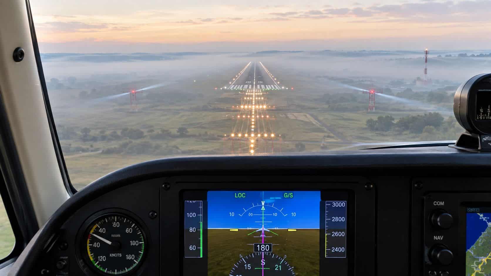
An ILS approach is a precision instrument approach that gives an aircraft both lateral and vertical radio guidance to align with a runway. Category I ILS operations use a decision height of 200 feet and visibility minimums no greater than 2,400 feet RVR, while more advanced categories support much lower visibility when the aircraft, crew, runway, and procedure are approved.
A pilot may be established inbound while the runway remains completely hidden behind cloud or haze. The instruments show whether the aircraft is left or right of the extended centerline and whether it's above or below the published descent path. That information turns a low-visibility arrival from a visual judgment exercise into a carefully managed IFR procedure.
The ILS remains important because it provides a stable, predictable path when visual references are limited. A good understanding goes beyond keeping two needles centered. Pilots also need to know how the system is constructed, how to brief and fly it, what decision height really means, how ground traffic can affect signal integrity, and why an approach can still be unavailable even when an airport has ILS equipment.
Two practical options worth comparing
These are specific products pilots commonly compare for this type of flying. Confirm compatibility with your aircraft and instructor before ordering.
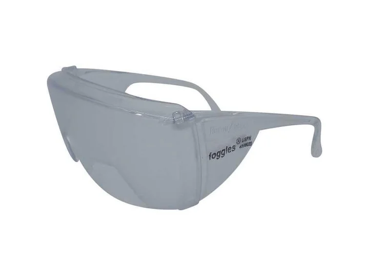 Instrument trainingFoggles Aviation IFR Training GlassesCheck current availability on Amazon (paid link)
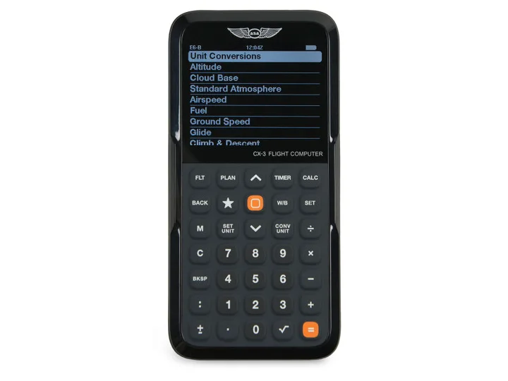 Flight planningASA CX-3 Flight ComputerCheck current availability on Amazon (paid link)
Table of Contents
- Understanding the ILS Approach in Real Weather
- The Core Components of an ILS
- How Pilots Fly the Approach
- ILS Categories and Landing Minimums
- Critical Areas and Operational Safety Risks
- The Future of ILS and Next Steps for Pilots
Understanding the ILS Approach in Real Weather
A ceiling can lower during a flight, or visibility can shrink before an aircraft reaches the terminal area. Under those conditions, a non-precision approach may provide lateral course guidance without a continuous electronic descent path. An ILS adds the vertical element, allowing the pilot to follow a defined path toward the runway while remaining in instrument conditions.
The Instrument Landing System is a precision approach aid. Its localizer provides lateral guidance, and its glide slope provides vertical guidance. Together, they create an electronic path that helps the aircraft align with the runway and descend toward the landing area.
The FAA description of instrument approach procedures explains that these procedures are approved to support a safe descent during instrument flight conditions. The ILS is therefore not merely a cockpit display. It's part of a larger system that includes ground transmitters, aircraft receivers, published approach data, runway lighting, operating minima, air traffic control, and pilot decisions.
Why the approach feels different from a non-precision procedure
On a lateral-only approach, the pilot must use published altitudes and fixes to control the descent. The aircraft may descend in steps, with each altitude serving as a protection against obstacles and terrain. An ILS normally provides a continuous descent path, so the pilot manages the aircraft around a geometric path rather than descending solely by reference to successive minimum altitudes.
That path still requires disciplined flying. A centered indication doesn't guarantee that the aircraft is configured correctly, stable, or legally able to land. The crew must verify the correct procedure, identify the approach, monitor the aircraft's response, and be prepared to go around if the runway environment isn't visible at the required point.
The practical value for instrument pilots
The ILS is useful because it reduces uncertainty, but it doesn't remove responsibility. The pilot still has to intercept the localizer from a suitable angle, capture the glide slope from below when required by the procedure, maintain a stable airspeed and descent, and cross-check altitude against the approach plate.
Students building that foundation can use DuBois Aviation's guide to instrument approach procedures alongside instructor-led practice. The essential habit is simple: treat the electronic path as guidance to be monitored, not as permission to continue.
Historically, ILS development took place over many stages. Research began in 1928, and on September 23, 1929, Army Lt. James Doolittle completed the first successful blind landing. The first modern VHF ILS installation was demonstrated by early 1940, while an industry reference identifies 1946 as the introduction of the ILS in its commonly recognized form and notes that roughly 25 more years of development were needed for the integrity required by advanced coupled approaches and landings. These milestones are documented in the FAA Pilot/Controller Glossary.
The Core Components of an ILS
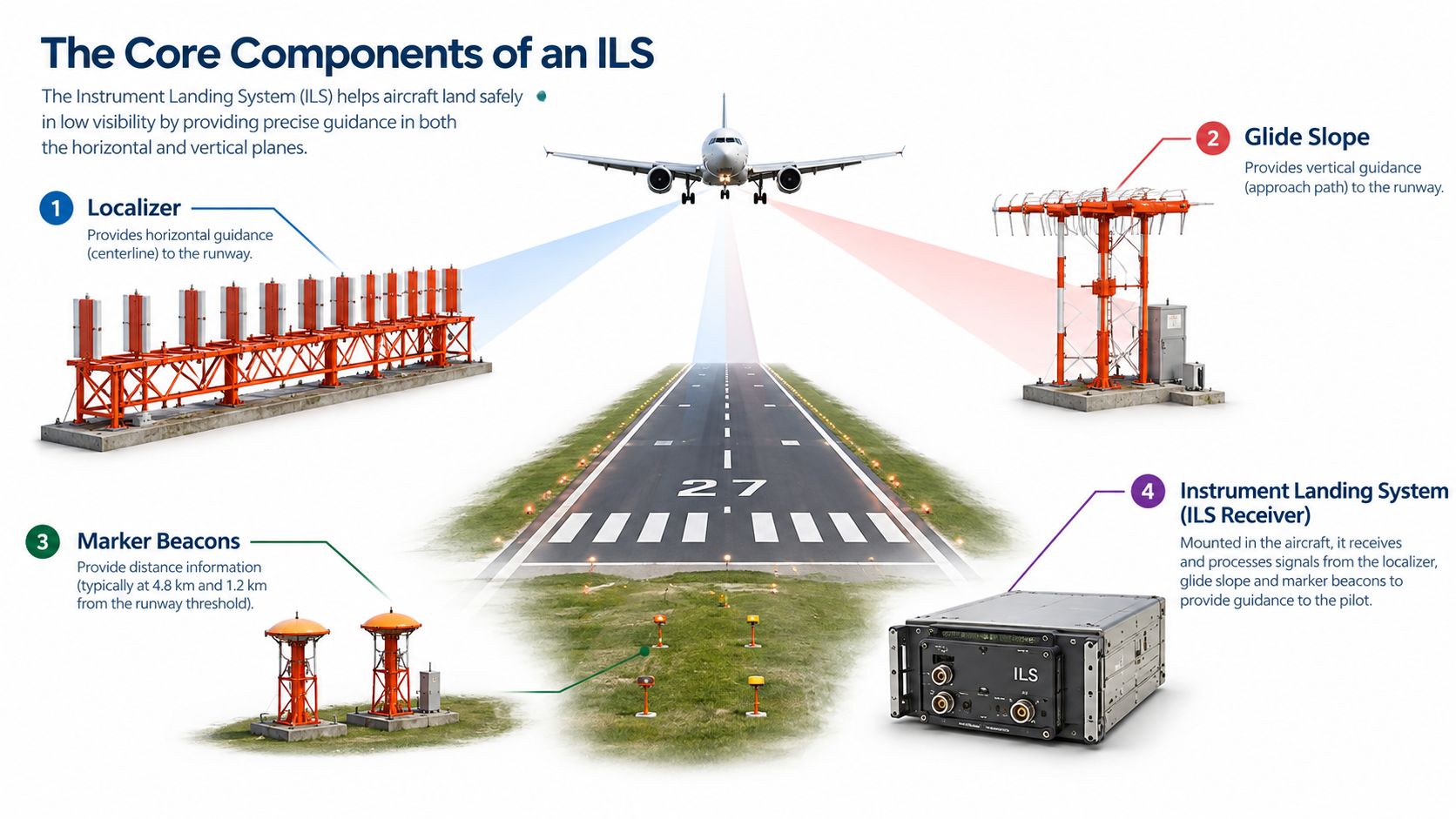
An ILS can be visualized as two invisible guides crossing in space. One guide runs along the runway centerline, and the other forms a descending plane above it. The aircraft receiver translates those radio signals into cockpit indications that show the pilot where the aircraft sits relative to the intended path.
Localizer guidance
The localizer provides lateral alignment with the runway centerline. Its transmitting equipment is positioned beyond the far end of the runway, so the aircraft flies toward the signal and receives guidance along the extended centerline.
In the cockpit, the localizer typically appears as a vertical course indication. If the indication moves to one side, the aircraft is displaced from the desired course. The pilot's correction should be proportional and deliberate. A small deviation close to the runway can require only a small heading adjustment, while a larger intercept farther out may need more correction.
The localizer isn't a magnetic runway heading substitute. Wind can require a crab angle, and the aircraft can remain properly aligned while its nose points slightly into the wind. The pilot's goal is to track the course over the ground, not to force the heading indicator to match the runway number.
Glide slope guidance
The glide slope supplies vertical guidance. Its antenna is normally located near the approach end of the runway, and the signal creates a descent path that the aircraft follows toward the threshold.
The FAA states that the glide path is normally set to a 3-degree descent angle. That path intersects the middle marker at about 200 feet above runway elevation and the outer marker at about 1,400 feet above runway elevation, as described in the FAA Aeronautical Information Publication.
The horizontal cockpit indication shows whether the aircraft is above or below the glide path. Above-path and below-path indications must be interpreted correctly, especially during interception. Capturing from above can encourage an aggressive descent and unstable energy state, which is why approach briefings and local procedures matter.
Markers and distance information
The FAA identifies the basic ILS components as the localizer, glide slope, Outer Marker, and, when installed for Category II or III procedures, Inner Marker. Marker beacons historically helped identify key points along final approach by giving the crew an audio and visual indication as the aircraft passed overhead.
Many procedures also provide distance information through other approved means shown on the approach chart. A pilot may use that information to verify crossing points, monitor progress, or identify a step-down fix when the procedure specifies it. The source of distance awareness must match the published approach and the aircraft's approved equipment.
The components work together, but each answers a different question:
- Localizer: Is the aircraft left or right of the runway centerline?
- Glide slope: Is the aircraft above or below the intended descent path?
- Markers or approved distance information: Where is the aircraft along the approach?
- Approach lighting and runway environment: Can the pilot legally continue at the published minimum?
A failure or unreliable indication in any part of the system changes the approach picture. Pilots must monitor annunciations, identify the procedure correctly, and follow the applicable aircraft and approach requirements rather than assuming that a signal is valid because a needle is moving.
How Pilots Fly the Approach
Flying an ILS well starts before the aircraft intercepts the final course. The pilot reviews the chart, confirms the navigation source, identifies the approach, checks altitudes and restrictions, and establishes a plan for configuration and missed approach execution.
Brief the approach before the workload peaks
A useful briefing answers practical questions:
- Which runway and procedure are active? Confirm the approach name, navigation frequencies or database selection, and final approach course.
- Where does the aircraft join the procedure? Identify the initial approach fix, intermediate segment, final approach fix, and any vectors-to-final expectations.
- What are the controlling altitudes? Note the minimum altitude at each relevant fix and the published decision altitude or decision height.
- What conditions permit landing? Review the required visibility, runway environment references, lighting, and any aircraft or crew limitations.
- What happens after a missed approach? Brief the initial climb, heading or course, altitude, and the point where further instructions are expected.
The approach plate is a task-management tool. It prevents the pilot from treating the final segment as an isolated needle exercise.
Intercept the localizer with room to stabilize
Vectors or procedure design normally place the aircraft on an intercept heading before the localizer becomes active. The pilot should avoid an unnecessarily steep intercept angle or excessive bank close to the final approach segment. Once the course begins to move, the correction should be smooth enough to prevent crossing through the centerline.
After the localizer is established, the aircraft should be configured according to the aircraft's operating procedures. Power, airspeed, trim, and drag must be coordinated before the glide slope becomes the dominant workload.
Capture and track the glide slope
A common training error is chasing the glide slope with large pitch changes. A better technique is to establish the aircraft near the published final approach speed, use small pitch and power adjustments, and allow the aircraft to settle onto the path.
Practical rule: Small deviations deserve small corrections. Large corrections often create a second deviation before the first one is solved.
The instrument scan should include the localizer, glide slope, airspeed, altitude, heading, vertical speed, engine instruments, and annunciations. The exact scan varies by aircraft and equipment, but the principle remains constant. The pilot flies the airplane first, then confirms that the guidance and automation are doing what the pilot expects.
Autopilot can reduce workload when its use is authorized and understood, but it can also conceal mode changes or an incorrect source selection. Pilots developing that discipline can review how to use an autopilot as part of broader instrument training, while still practicing the approach manually.
Manage energy and prepare to go missed
A stable ILS approach requires the aircraft to arrive at the decision point in a condition from which a landing or missed approach can be performed without improvisation. Excessive speed, high sink rate, late configuration, or large heading corrections should prompt an early correction or a go-around according to the applicable procedures.
At decision altitude or decision height, the result is binary. If the required visual references are in sight and all landing conditions are satisfied, the pilot may continue. If they aren't, the pilot must execute the published missed approach rather than descend farther in the hope that the runway will appear.
ILS Categories and Landing Minimums
ILS categories describe the level of precision and low-visibility capability available to an approved combination of runway, equipment, aircraft, and crew. The category isn't selected by preference in the cockpit. The published procedure and authorization determine which minima apply.
The FAA's published values distinguish the categories as follows:
| ILS Category | Decision Height (DH) | Runway Visual Range (RVR) |
|---|---|---|
| Category I | 200 feet | 2,400 feet |
| Category II | 100 feet | 1,200 feet |
| Category IIIA | No DH or below 100 feet | Not less than 700 feet |
| Category IIIB | No DH or below 50 feet | 150 to 700 feet |
| Category IIIC | No DH | No RVR limitation |
These values are provided in the FAA ILS minimums reference. ICAO material describes corresponding metric thresholds, including CAT IIIA with a decision height below 100 feet and RVR not less than 175 m, CAT IIIB below 50 feet with RVR between 50 m and 175 m, and CAT IIIC with no decision height or RVR limit. The FAA Aeronautical Information Manual also describes the progression from CAT I through CAT IIIA, IIIB, and IIIC.
Decision height is a hard boundary
Decision height isn't a point where the pilot can continue searching visually. It's the lowest point at which the pilot must have the required visual references to continue the landing under the applicable procedure. Without those references, the missed approach begins immediately.
Category I operations are common in general aviation because they require less specialized aircraft capability, crew training, and airport infrastructure than lower-minimum operations. Even so, the runway must meet the published requirements, and the pilot must confirm that weather, equipment status, and aircraft approval support the intended approach.
Why equipment and authorization matter
A runway may display ILS indications without supporting every category. The aircraft may lack approved equipment, the crew may not hold the required authorization or training, or the runway lighting and monitoring status may restrict the available minima.
The same aircraft can therefore face different operating limits on different runways. Pilots should read the approach chart, review current notices affecting the procedure, and apply the aircraft flight manual, operating specifications, and regulations that govern the flight. Currency also matters, so pilots should keep the requirements for IFR currency separate from the question of whether a particular ILS category is authorized.
Critical Areas and Operational Safety Risks
An ILS signal can be accurate while the operation around it remains unsafe or unstable. The most overlooked example is the ILS critical area, a protected zone near the localizer and glide slope equipment where aircraft and vehicles can interfere with signal quality.
Why ground movement matters
Large metal objects near transmitting equipment can distort the signal that creates the localizer or glide slope path. The aircraft may then receive guidance that is less reliable than it appears, especially during the part of the approach when the pilot is making small corrections close to the centerline.
FAA safety guidance says ATC must protect the ILS critical area when an aircraft is on an approach inside the final approach fix and weather is at or below 800 feet or 2 miles. At a towered airport, the protection normally appears through hold-short instructions or other controller coordination. Pilots must read back and comply with those instructions, and taxiing crews must understand that a hold-short line can protect more than runway separation.
The operational point is easy to miss. A vehicle or aircraft doesn't need to collide with an antenna to create a problem. Entering a protected area at the wrong time can affect the signal and increase the likelihood of a deviation, unstable approach, or go-around.
Towered and uncontrolled airports are different
The FAA safety notice on ILS critical areas notes that critical-area protection is mandatory when ATC issues the hold instruction. At an uncontrolled airport, there isn't a formal ATC requirement to hold short in the same way, so pilots must use judgment based on traffic, weather, airport markings, published information, and the likelihood that ground movement could affect the approach.
That doesn't mean an uncontrolled field is automatically unsafe for an ILS. It means the pilot has to build the ground environment into the approach briefing. Before starting the procedure, the crew should consider whether aircraft or vehicles could enter the critical area, whether the airport communicates relevant activity, and whether a missed approach or delay is preferable to accepting uncertain guidance.
Weather affects the operation more than the radio beam
Rain, cloud, and reduced visibility don't usually corrupt the ILS radio signal in the same way that an object entering a critical area can. The bigger operational effects are reduced visual acquisition, wet or contaminated pavement, and diminished braking performance. Those factors influence whether the aircraft can continue, land, or safely exit the runway.
The human-factors hazard becomes most serious near decision altitude. Continuation bias can make a pilot keep descending because the runway feels likely to appear, because the approach has consumed time and effort, or because traffic pressure makes a missed approach feel inconvenient.
At decision altitude, hope isn't a landing reference.
A pilot who doesn't have the required visual cues must initiate the missed approach. The correct response isn't to dip below minimums for another look. It's to apply power, follow the published missed approach, and communicate with ATC when workload permits.
Common mistakes worth correcting early
- Chasing the needles: Large corrections can produce oscillations. Use small, coordinated changes and monitor trends.
- Ignoring the ground environment: A correct clearance doesn't eliminate the need to understand critical-area protection.
- Treating autopilot engagement as success: Automation must be monitored for correct mode, source, and tracking.
- Continuing below DA or DH: The runway environment must be visible before continuation is authorized.
- Skipping current status checks: A procedure can be affected by maintenance, notices, weather, or airport limitations.
The Future of ILS and Next Steps for Pilots
Satellite-based procedures continue to expand, but ILS remains a significant tool for low-visibility operations because its guidance comes from ground-based equipment rather than satellite reception. Its role is especially important where operators value a highly standardized precision approach and where the runway, aircraft, and crew support the applicable category.
Availability isn't guaranteed forever. In September 2026, local reporting said Allen County Airport was trying to keep its ILS approach open while the FAA considered closing it because of low utilization, as described by the Allen County Airport report. That example illustrates an operational reality for pilots: an ILS procedure can be affected by utilization, maintenance demands, airport economics, and regulatory decisions.
Build proficiency beyond needle movement
A pilot preparing for instrument privileges should practice the complete operation:
- Brief the chart: Identify fixes, altitudes, minima, missed approach instructions, and required equipment.
- Fly stable intercepts: Use appropriate headings and avoid aggressive corrections close to final.
- Monitor automation: Confirm the selected source, active mode, and actual aircraft response.
- Practice missed approaches: Rehearse the decision before reaching minimums.
- Use realistic workload: Include radios, configuration, checklists, traffic, and changing weather in training.
- Review local procedures: Busy towered environments add communication and ground-movement demands that a quiet practice area may not reproduce.
Simulator sessions can isolate scan, automation, and missed-approach skills, while dual instruction adds real aircraft handling and operational judgment. The strongest instrument pilots don't merely memorize where the needles should sit. They recognize when the approach is becoming unstable, when the signal environment is uncertain, and when continuing would require an unsafe assumption.
An ILS approach is a precision path, not a promise that the runway will be available. The pilot's job is to use the guidance accurately, respect the published minimums, protect the aircraft from unstable energy states, and execute the missed approach without hesitation when the required visual references aren't there.
DuBois Aviation provides instrument training that includes precision approaches such as ILS, along with other instrument procedures, using airplane instruction, simulator practice, and training at a busy towered airport environment. Pilots can visit DuBois Aviation to ask about instrument-rating availability, aircraft rental, or a training plan focused on confident IFR decision-making.


